
DIY: LED swap Tutorial (No 56k!!)


Thread Starter
Senior Member
Defined3
SL Member
Joined: Apr 2004
Posts: 945
From: Philly, PA
Disclaimer: I'm NOT responsible for any damage done to your vehicle.
Let�s get started
IF you never solder or are not comfortable with soldering;
1. Please read some tutorials.
Soldering Tutorials 1
Soldering Tutorials 2
2. Practice. I like to practice with some old/broke circuit boards, there�s no risk in braking what�s already broken!!
3. Patience. Please Take your time and look at what you�re going to be removing/modding.
Tools:
1. Solder Station. Any Solder Station will do. I recommend weller solder stations. Remember most of the components are very small so get a station that is able have different Tips.
2. Solder Wick/Braid. Get here.
3. Reverse Action Tweezers These are great for soldering Small components. Get here.
4. Solder.
Parts:
Most of the LEDs we�re going to be changing are �PLCC-2�.
I buy mine from ebay, Great Price and great turnouts!! Here�s who I use
HKJE LED Lamp Center.
Let�s get started!!
Follow these steps and Get associated with the gauges as we go along.
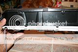
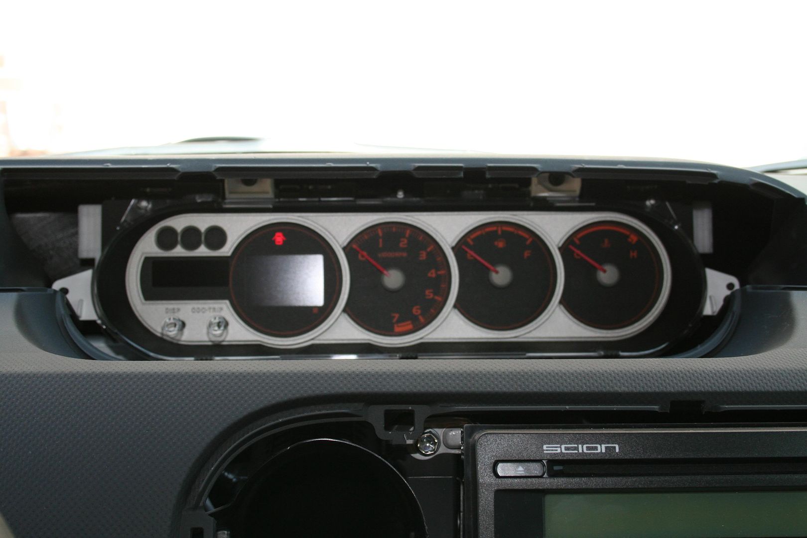
Here�s what it looks like all pretty and new!
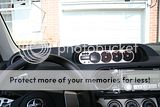
Remove the Gauge Cover. Remove 4 Screws.

Remove the Gauge Connectors.
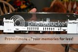
Remove 8 Screws and back cover.
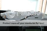
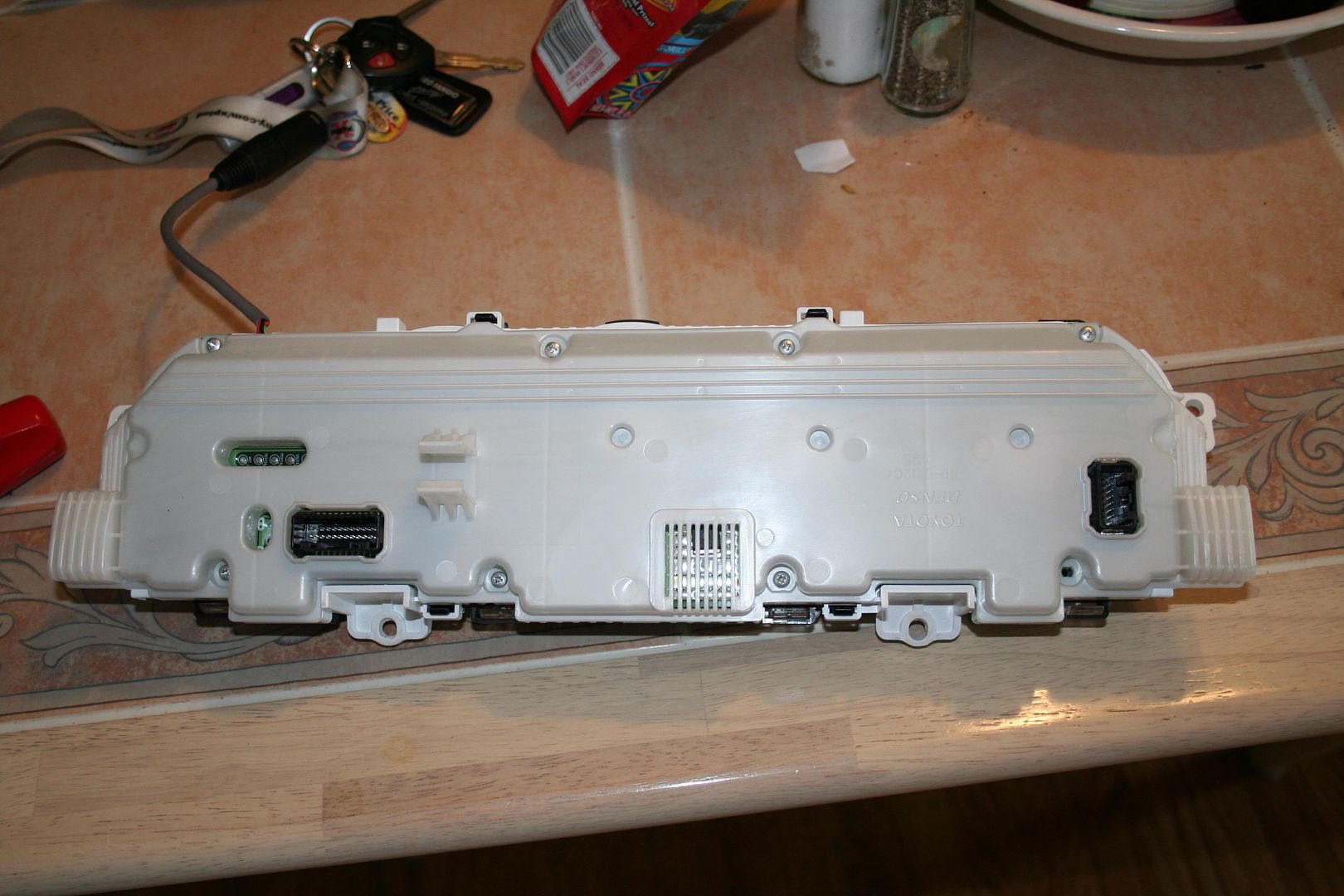
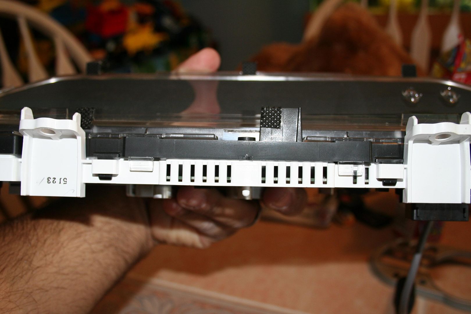
Here�s what you�re looking at when the cover is removed.
Press Slightly on the Black Tabs to Remove the Front Cover. There�s 4 Tabs, 2 at the bottom and 2 at the top.
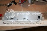
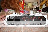
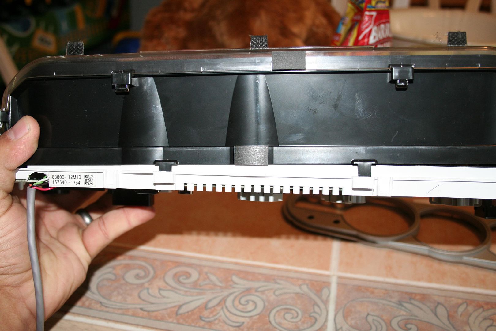
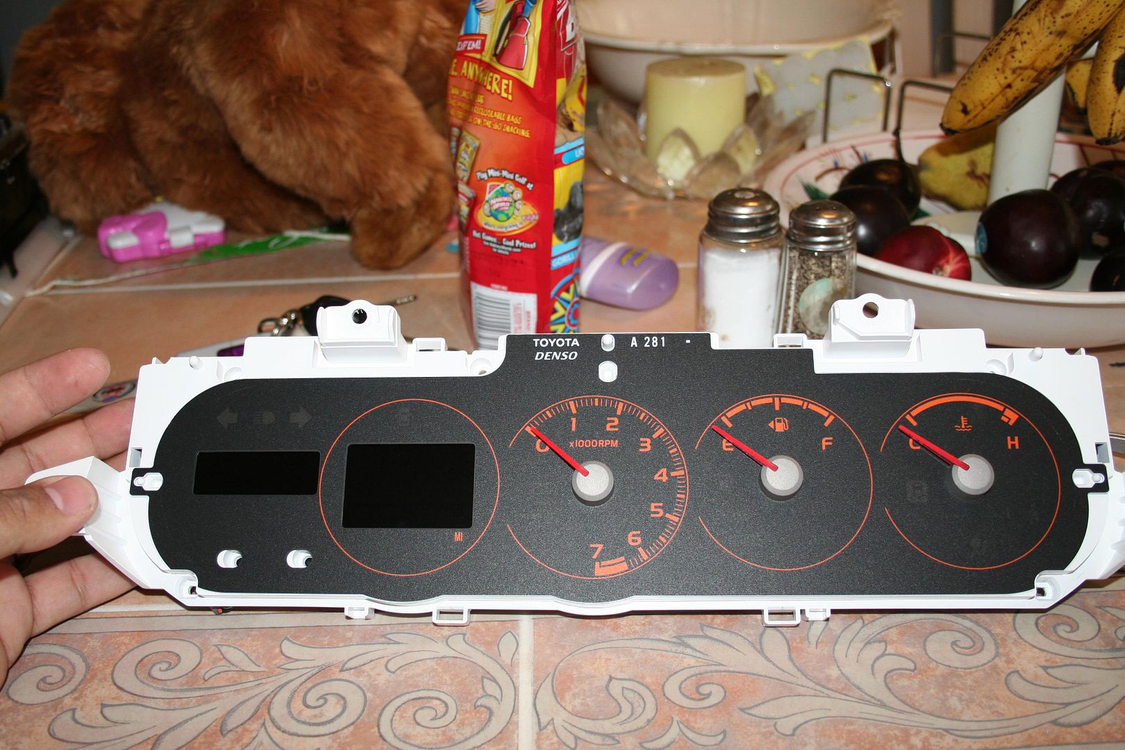
Here�s what we�re looking at now. Remember where the needles sit. Remove the Needles and Gauge face plate.
Let�s Remove the Circuit Board from the housing. The board should come out easily except for the section where the LCDs are connected. I used a small Flat head Screw drive to pry the circuit board out. BE PATIENT AND TAKE YOUR TIME!!!!!
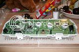
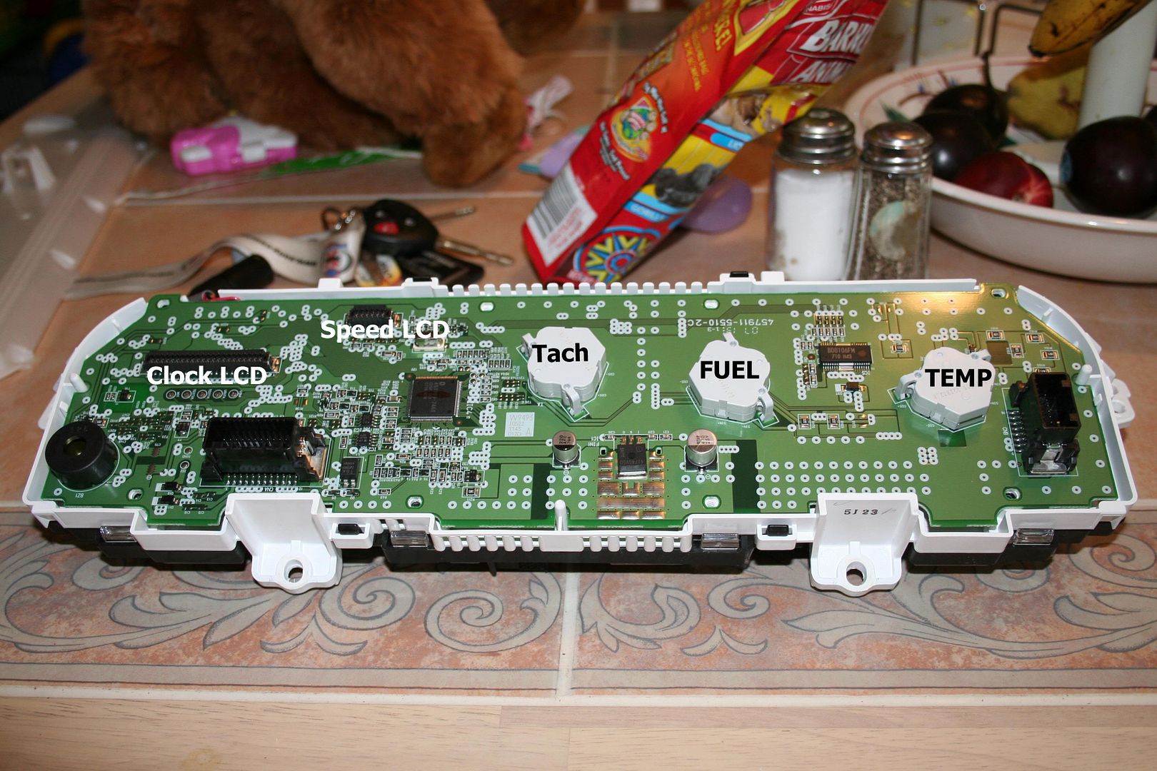
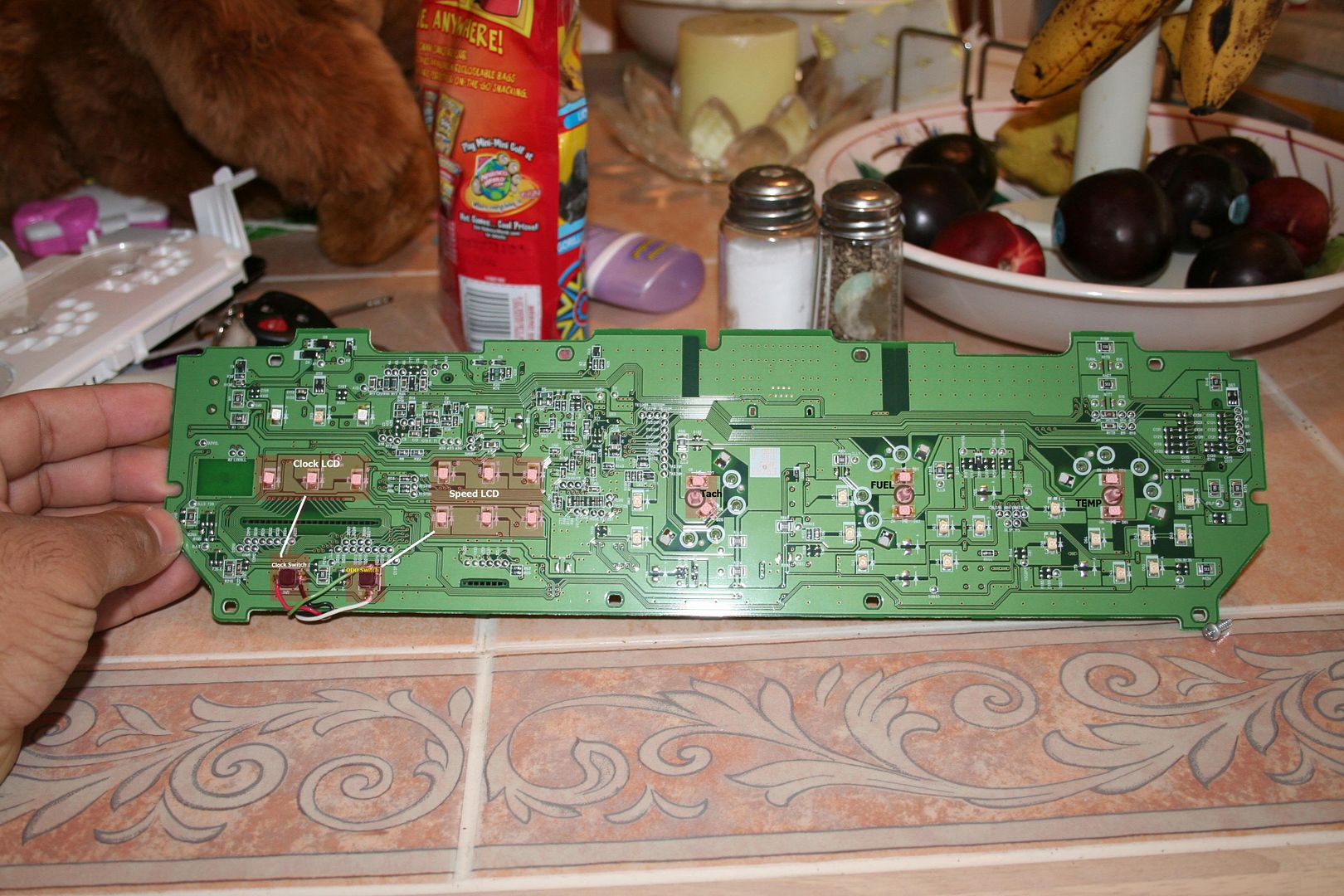
Here�s the Circuit Board in all its Glory. Cue the Mystical Music. �AHahahahaAHahaHah�.
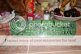
And here�s what everything is.

Apply the solder iron tip each side the LED one at a time. If the LED doesn�t Budge use some solder wick.
Once LED is removed, apply Solder to the silver pad, if you put to much remove it with the solder wick and try again.
NOTE:
The LED will have a small notch at one corner. That tell you that Cathode leg of the LED. Face the Notch towards the Cathode Drawing on the circuit board.

Place the new LED in between the silver pad while holding the LED with the Reverse action Tweezers, hit each Leg of the LED with the solder iron to solder the LED in place.
Repeat for all other LEDs you want to replace.
Here�s the Finished product.

Any comments please PMME.
Let�s get started
IF you never solder or are not comfortable with soldering;
1. Please read some tutorials.
Soldering Tutorials 1
Soldering Tutorials 2
2. Practice. I like to practice with some old/broke circuit boards, there�s no risk in braking what�s already broken!!
3. Patience. Please Take your time and look at what you�re going to be removing/modding.
Tools:
1. Solder Station. Any Solder Station will do. I recommend weller solder stations. Remember most of the components are very small so get a station that is able have different Tips.
2. Solder Wick/Braid. Get here.
3. Reverse Action Tweezers These are great for soldering Small components. Get here.
4. Solder.
Parts:
Most of the LEDs we�re going to be changing are �PLCC-2�.
I buy mine from ebay, Great Price and great turnouts!! Here�s who I use
HKJE LED Lamp Center.
Let�s get started!!
Follow these steps and Get associated with the gauges as we go along.
Here�s what it looks like all pretty and new!

Remove the Gauge Cover. Remove 4 Screws.
Remove the Gauge Connectors.

Remove 8 Screws and back cover.
Here�s what you�re looking at when the cover is removed.
Press Slightly on the Black Tabs to Remove the Front Cover. There�s 4 Tabs, 2 at the bottom and 2 at the top.
Here�s what we�re looking at now. Remember where the needles sit. Remove the Needles and Gauge face plate.
Let�s Remove the Circuit Board from the housing. The board should come out easily except for the section where the LCDs are connected. I used a small Flat head Screw drive to pry the circuit board out. BE PATIENT AND TAKE YOUR TIME!!!!!
Here�s the Circuit Board in all its Glory. Cue the Mystical Music. �AHahahahaAHahaHah�.

And here�s what everything is.
Apply the solder iron tip each side the LED one at a time. If the LED doesn�t Budge use some solder wick.
Once LED is removed, apply Solder to the silver pad, if you put to much remove it with the solder wick and try again.
NOTE:
The LED will have a small notch at one corner. That tell you that Cathode leg of the LED. Face the Notch towards the Cathode Drawing on the circuit board.
Place the new LED in between the silver pad while holding the LED with the Reverse action Tweezers, hit each Leg of the LED with the solder iron to solder the LED in place.
Repeat for all other LEDs you want to replace.
Here�s the Finished product.
Any comments please PMME.
Thread Starter
Senior Member
Defined3
SL Member
Joined: Apr 2004
Posts: 945
From: Philly, PA
When putting everything back together. remember where the needles went, if you forgot, here's a tip.
Tach needle falls right on top of the "0" and the first line.
Fuel needle falls right on top of the "E".
Temp needle falls right on top of the "C".
Also Remember that the needle has too have tension when you move the needle counter-clockwise. and also move the needle counter-clockwise to adjust the settings.


Senior Member
SL Member
Joined: May 2007
Posts: 249
From: NorCal - East Bay - (925)
cool. I just sent you a PM. If you could send me your hi-res pics of both I would love to see them. My brother and I both have xb's and those are the same two colors we want to do. I want blue he wants green.
I am trying to decide whether I need to get the guage face overlay or not, hoping your pics will help me out there.
I am trying to decide whether I need to get the guage face overlay or not, hoping your pics will help me out there.


Senior Member
SL Member
Joined: Jul 2007
Posts: 967
From: St Louis
Originally Posted by lvbitwiz
Just a walk in the park (sorry for the poor quality image)

tell me that's not the norm... dasaints guages are bright & youcan actually see how much fuel you have & such.. but not yours...??? any feedback please,,... thanks.. I am supposed to have mine done on Thursday
.... jh

are these the correct leds to use?? or did I get the wrong ones.... they look awfully small....

thanks agian... jh

Senior Member
SL Member
Joined: Aug 2006
Posts: 1,066
From: Vegas baby!
They are lit, used the same type leds as dsaint. They will be dimmer that the speedo face but that is due to the orange filtering on the numbers. The reasone you cannot see it too well in my photo is that I shot it on full auto settings. Next time Ill snap it on night mode and let the shutter stay open for a couple seconds, then it'll show better.
Senior Member
SL Member
Joined: Jul 2007
Posts: 967
From: St Louis
did you look at my pictures of my LED's, lvbitwiz......?? are they the same.. I gotta know before I keep my apontment for my swap.......... can you tell by my photos if they are the same as the ones you put in yours.. I put my key in the shot for reference... thanks for your prompt reply, dude!!!.. jh

Former Sponsor
SL Member

Joined: Apr 2006
Posts: 2,093
From: Anaheim, CA & Las Vegas
Originally Posted by jimmbomb
lvbitwiz..... your guages arent lighting up.. now nearly at all as compared to dasaints's?? how come is that?? I mean your digital readout is lit.. but the circular guages are not lit at all.. you can barely see your needles even...
tell me that's not the norm... dasaints guages are bright & youcan actually see how much fuel you have & such.. but not yours...??? any feedback please,,... thanks.. I am supposed to have mine done on Thursday
tell me that's not the norm... dasaints guages are bright & youcan actually see how much fuel you have & such.. but not yours...??? any feedback please,,... thanks.. I am supposed to have mine done on Thursday
dasaints' photo is over exposed... that's why it's so much brighter....
Also it doesn't light up blue.. it's like dim greenish blue....
It's cause by the stock gauge face being amber color... blue and amber color don't mix well..
You'll need new gauge face that outputs the blue lights properly....
Exmaple here...


