
LED Swap (05-06 HVAC w/Circuit MOD)


Thread Starter
Senior Member
Scikotics
SL Member
Joined: Nov 2004
Posts: 9,731
From: Minneapolis, MN
** Edited to add some info and fix some typo's... I am sure I will find more later  ***
***
This is the newest incarnation of the HVAC mod for running blue, green or white LEDs. If some of the replies and discussions following seem out of place, it is because I am replacing my old mod with this one in order to keep one thread out there for this. I will create a separate one for the 2007 and ask for it to be moved to the tech section as well. If you are running red LEDs or are only swapping the gauge LEDS, then you do not need to perform this mod.
I have calculated the circuit components and obtained datasheets for the power supply IC, so I am confident it is all in spec and properly designed. As with all of these DIY posts, I take no responsibility for anything (broken LCD, wife leaving you, meteor falling on your house, etc ) I have 6 years of schooling and 2 degrees in the areas of electronics engineering (telecommunications and control systems) and engineering management, for those leary of taking someone on the internets mod and applying it to your baby But like I said, be careful not to damage anything while working. I reccomend taking static precautions since you are working around static sensitive devices, using a soldering iron with proper ESD protection, etc. I have been running this mod in my car for about a month now.
Before beginning, it is a good idea to determine if this is a job you want to tackle if you do not have a lot of experience with this. Below is a list of what is involved:
1. De-soldering the LCD for the clock. This is probably one of the more tedious pieces. This takes some patience to do right and can result in a broken LCD, which is replacable only through purchasing an entire HVAC module. So be careful on this step!
2. De-soldering all LEDs and some surface mount resistors. These parts are very small, so be ready to work with tweezers.
3. Soldering the new parts back in and soldering in the LCD
Tools you will need for this:
1. Soldering iron: 25-30W is plenty. Work quickly if you use a 30W iron. A temperature controlled iron is recommended, but I realize many may not want to spend $150 or so for one of these. You will need a small pointed tip for this (if using Cooper/Weller irons, I recommend an ETO or ETA tip).
2. Solder sucker: You can purchase a cheap one that is heated from Radio Shack or a similar store for around $10. Solder wick works great as well, but if you are not experience using it, the sucker may be a better option
3. Solder: You will need a small gauge solder for this.
4. Tweezers
5. Needle nose pliers: to remove the temp **** lock nut
Parts needed for the 2005-2006 HVAC board
16 - PLCC-2 LEDS (18 if you want to do the gradient effect on the temp ****)
3 � 1206 package 43 Ohm SMT resistors
1 � 1206 package 130 Ohm SMT resistor
1 � 1206 package 420 Ohm SMT resistor
1 � 1206 package 680 Ohm SMT resistor
1 � 1206 package 560 Ohm SMT resistor
1 � SP-3SU package +10V regulator 1.2A rating
Ok, lets get started.
I dont reccomend this if you are not familiar with or comfortable with soldering and wiring. I wont go through soldering techniques or dissasembling the console, as this has already been covered in these other posts.
https://www.scionlife.com/forums/vie...=37747&start=0
https://www.scionlife.com/forums/vie...=61793&start=0
I will focus on the circuit design. I will note one thing though. Be VERY patient with the LCD. Use solder wick and/or a desoldering iron, and move from one end to the other so you are not focusing heat on one area too long. It will seem they will never come loose, but there is solder all the way through, so it takes a while to get it all out. Dont try removing it until you can see all pins on the bottom move when you wiggle the display.
1. On the front of the board, de-solder the following parts:
a. R304 � Top left side of board, marked in red in Figure 1 below
b. R307 � Left of clock LCD. Marked in red in Figure 2 below
c. R312 � upper left of TEMP **** LEDs. Marked in red in Fig 3
d. R310 � Upper Right. Marked in Red if Figure 4 below
e. All LEDs you will be swapping
2. On the back of the board, de-solder the following:
a. R306 � Marked in red in figure 5 below. Middle � Right side
b. R314 � Behind the temp ****, marked in red in Figure 6
c. R316 � Behind the temp ****, marked in red in Figure 6
d. IC300 � Middle Right. Marked in Green in Figure 5
3. Replace the removed components with the new values listed below:
a. All LEDS removed previously
b. R304: 1206 package 43 Ohm SMT resistor
c. R310: 1206 package 43 Ohm SMT resistor
d. R306: 1206 package 43 Ohm SMT resistor
e. R307: 1206 package 130 Ohm SMT resistor
f. R312: 1206 package 420 Ohm SMT resistor
g. R314: 1206 package 560 Ohm SMT resistor
h. R316: 1206 package 680 Ohm SMT resistor
i. IC300: SP-3SU package +10V regulator 1.2A rating
4. This is a good time to plug the unit back in and test. Make sure to push all of the buttons and test all functions now so you don�t end up taking it back apart later.
5. Solder the LCD back into place. Be careful to move end to end while soldering so as not to overheat one area.
6. Clean all connections with rubbing alcohol and dry thoroughly
7. Plug in to test once again
8. Re-assemble HVAC module, install and enjoy!
Figure 1:

Figure 2:

Figure 3:
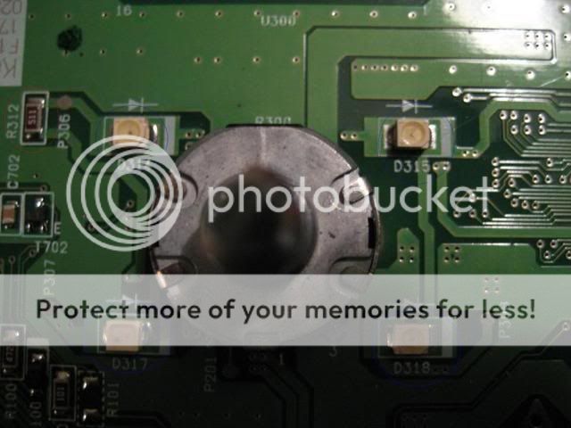
Figure 4:

Figure 5:

Figure 6:

And my personal reccomendation for a finish (if you are old enough )

This is the newest incarnation of the HVAC mod for running blue, green or white LEDs. If some of the replies and discussions following seem out of place, it is because I am replacing my old mod with this one in order to keep one thread out there for this. I will create a separate one for the 2007 and ask for it to be moved to the tech section as well. If you are running red LEDs or are only swapping the gauge LEDS, then you do not need to perform this mod.
I have calculated the circuit components and obtained datasheets for the power supply IC, so I am confident it is all in spec and properly designed. As with all of these DIY posts, I take no responsibility for anything (broken LCD, wife leaving you, meteor falling on your house, etc
Before beginning, it is a good idea to determine if this is a job you want to tackle if you do not have a lot of experience with this. Below is a list of what is involved:
1. De-soldering the LCD for the clock. This is probably one of the more tedious pieces. This takes some patience to do right and can result in a broken LCD, which is replacable only through purchasing an entire HVAC module. So be careful on this step!
2. De-soldering all LEDs and some surface mount resistors. These parts are very small, so be ready to work with tweezers.
3. Soldering the new parts back in and soldering in the LCD
Tools you will need for this:
1. Soldering iron: 25-30W is plenty. Work quickly if you use a 30W iron. A temperature controlled iron is recommended, but I realize many may not want to spend $150 or so for one of these. You will need a small pointed tip for this (if using Cooper/Weller irons, I recommend an ETO or ETA tip).
2. Solder sucker: You can purchase a cheap one that is heated from Radio Shack or a similar store for around $10. Solder wick works great as well, but if you are not experience using it, the sucker may be a better option
3. Solder: You will need a small gauge solder for this.
4. Tweezers
5. Needle nose pliers: to remove the temp **** lock nut
Parts needed for the 2005-2006 HVAC board
16 - PLCC-2 LEDS (18 if you want to do the gradient effect on the temp ****)
3 � 1206 package 43 Ohm SMT resistors
1 � 1206 package 130 Ohm SMT resistor
1 � 1206 package 420 Ohm SMT resistor
1 � 1206 package 680 Ohm SMT resistor
1 � 1206 package 560 Ohm SMT resistor
1 � SP-3SU package +10V regulator 1.2A rating
Ok, lets get started.
I dont reccomend this if you are not familiar with or comfortable with soldering and wiring. I wont go through soldering techniques or dissasembling the console, as this has already been covered in these other posts.
https://www.scionlife.com/forums/vie...=37747&start=0
https://www.scionlife.com/forums/vie...=61793&start=0
I will focus on the circuit design. I will note one thing though. Be VERY patient with the LCD. Use solder wick and/or a desoldering iron, and move from one end to the other so you are not focusing heat on one area too long. It will seem they will never come loose, but there is solder all the way through, so it takes a while to get it all out. Dont try removing it until you can see all pins on the bottom move when you wiggle the display.
1. On the front of the board, de-solder the following parts:
a. R304 � Top left side of board, marked in red in Figure 1 below
b. R307 � Left of clock LCD. Marked in red in Figure 2 below
c. R312 � upper left of TEMP **** LEDs. Marked in red in Fig 3
d. R310 � Upper Right. Marked in Red if Figure 4 below
e. All LEDs you will be swapping
2. On the back of the board, de-solder the following:
a. R306 � Marked in red in figure 5 below. Middle � Right side
b. R314 � Behind the temp ****, marked in red in Figure 6
c. R316 � Behind the temp ****, marked in red in Figure 6
d. IC300 � Middle Right. Marked in Green in Figure 5
3. Replace the removed components with the new values listed below:
a. All LEDS removed previously
b. R304: 1206 package 43 Ohm SMT resistor
c. R310: 1206 package 43 Ohm SMT resistor
d. R306: 1206 package 43 Ohm SMT resistor
e. R307: 1206 package 130 Ohm SMT resistor
f. R312: 1206 package 420 Ohm SMT resistor
g. R314: 1206 package 560 Ohm SMT resistor
h. R316: 1206 package 680 Ohm SMT resistor
i. IC300: SP-3SU package +10V regulator 1.2A rating
4. This is a good time to plug the unit back in and test. Make sure to push all of the buttons and test all functions now so you don�t end up taking it back apart later.
5. Solder the LCD back into place. Be careful to move end to end while soldering so as not to overheat one area.
6. Clean all connections with rubbing alcohol and dry thoroughly
7. Plug in to test once again
8. Re-assemble HVAC module, install and enjoy!
Figure 1:
Figure 2:
Figure 3:
Figure 4:
Figure 5:
Figure 6:
And my personal reccomendation for a finish (if you are old enough


Senior Member
SL Member
Joined: Feb 2005
Posts: 2,087
From: St. Louis, MO
This has to be sent to the SL August contest Engi....Here are the details below. This "how to" has at last properly fixed an issue that has been a thorn for a year now, and it's done dead on professional. The console blue and white LED issue is no longer.  Be sure to email the link to him for submission. Nice job.
August Contest
OK guys, this month I am going to be adding to our tech article library by giving a prize to the member that creates the best new tech article for the website. It should contain step-by-step instructions with photos. It can be ANYTHING, as long as it doesn't already exist in our library. Check our current tech library here:
www.scionlife.com/tech
You will need to create a new topic somewhere in the forums and then you must EMAIL me the link to your article.[/b][/b]
-=PRIZE=-
The prize for this month's contest is your choice of the following:
- A Hotchkis lowering spring kit for your Scion model courtesy of www.hotchkistuning.com
- A Tanabe Strut Tower Bar for your tC or xA/xb courtesy of www.tanabe-usa.com
- An AudioFormz custom cargo panel painted to match your stock color xB courtesy of www.audioformz.com
- An OEM Scion Red Leather xA/xB Steering wheel courtesy of www.scionevolution.com
- An OEM Scion xB-Plus Security System courtesy of www.scionevolution.com
- A set of OEM xA factory fog lights courtesy of www.scionevolution.com
- A one-year Premium Membership to Scion Life with Prize Pack ($200 value)
-=RULES=-
- Article must be helpful and not a "spoof", although humor is always a plus
- Images will be transferred to the SL server as soon as we can for archiving
- You may enter as many times as you wish
-=JUDGING=-
As always I am the sole judge and my decision is final. Live with it.
Senior Member
SL Member
Joined: Feb 2005
Posts: 2,087
From: St. Louis, MO


Thread Starter
Senior Member
Scikotics
SL Member
Joined: Nov 2004
Posts: 9,731
From: Minneapolis, MN
Originally Posted by ScionDad
Hey, I see you have a full tank of gas. Pretty soon, we will need a line of credit to fill up. 
As far as more pics, I will be doing the other board I have this week hopefully, so I will take even more then and post them.
And somebody mentioned here or on the other thread about the stereo... I am actually thinking of just doing the readout on it. I think the buttons accent the amber needles and heat control nicely.. plus there are a million of them


Senior Member
SL Member
Joined: Feb 2005
Posts: 202
This might be off topic but I need a Guage LED fix. First off, I praise the work you have done engifineer
I just installed Blue LEDS into the guage and everything looks great.. Except I now have a check engine light with what it seems like a loss of power when my car is idle. Also my speedometer does not go up when I accelerate. All other guages work fine. Anyone know what it could be? How can a LED conversion set off the check engine light? Sorry if this is off topic but please help and advise if you guys can. Thanks in advance.
I just installed Blue LEDS into the guage and everything looks great.. Except I now have a check engine light with what it seems like a loss of power when my car is idle. Also my speedometer does not go up when I accelerate. All other guages work fine. Anyone know what it could be? How can a LED conversion set off the check engine light? Sorry if this is off topic but please help and advise if you guys can. Thanks in advance.
Senior Member
SL Member
Joined: Feb 2005
Posts: 202
Originally Posted by engifineer
Look for damaged connections and little peices of solder on the board and between pins of the ICs on the board. That would be the most logical place to look.


Member
SL Member
Joined: Jul 2005
Posts: 42
Originally Posted by johnnyTCblaze
This might be off topic but I need a Guage LED fix. First off, I praise the work you have done engifineer
I just installed Blue LEDS into the guage and everything looks great.. Except I now have a check engine light with what it seems like a loss of power when my car is idle. Also my speedometer does not go up when I accelerate. All other guages work fine. Anyone know what it could be? How can a LED conversion set off the check engine light? Sorry if this is off topic but please help and advise if you guys can. Thanks in advance.
I just installed Blue LEDS into the guage and everything looks great.. Except I now have a check engine light with what it seems like a loss of power when my car is idle. Also my speedometer does not go up when I accelerate. All other guages work fine. Anyone know what it could be? How can a LED conversion set off the check engine light? Sorry if this is off topic but please help and advise if you guys can. Thanks in advance.