The Supercharger Thread™ (non-TRD)
 05-03-2015, 09:26 PM
#1
Senior Member
SL Member
Thread Starter

Join Date: Aug 2009
Posts: 120
I'm installing an Eaton M62 supercharger in my 2009 Scion xB. Here's the exact unit I'm using, bought refurbished with a bottle of fluid for $193.78:
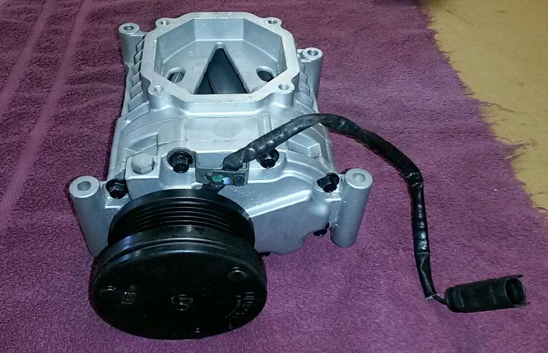
These units are absolutely ideal because they are:
1. Incredibly cheap
The reason they are cheap is that they used a special clutched 3.75" pulley that has no aftermarket support, so no one wants to mess with them. It may turn out that having a 7th groove added to the original pulley (it's a 6 groove unit) would be the best option, since that's about the right size pulley for our belt setup. I'm starting with a 3.85" modular edelbrock pulley, and making a custom adapter hub is still one of the big to-do items. I'll know in the end if the original was in fact the correct size (the math suggests so).
2. Properly sized for our engine
The M62 is designed for engines in the 2.0 to 4.0 liter range, and they are very efficient (compared to centrifugal superchargers) at low pressure (I'm aiming for around 5.5 PSI) at reasonably low RPM range. I was originally looking a the Eaton M45, but the M62 can be spun much slower and provide the same output.
3. Reliable
These are OEM units that are designed and sold for long term OEM operation. Not only are they likely to last longer, but rebuilds and rebuilt units can often be had for a fraction of the cost of the rebuild or replacement of a turbo.
4. Upgradeable
A roots style supercharger provides a very linear increase in airflow which can be adjusted dramatically by changing the pulley size. This is very different from a turbocharger in that there isn't really a complex compressor map; it's basically a straight line. In theory, the M62 could provide over 14 PSI intercooled with a smaller pulley, which is way beyond what the stock engine (and probably transmission) can handle.
Progress:
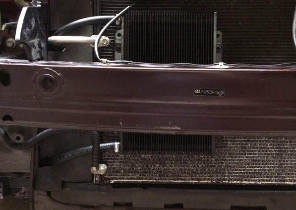
* The intercooler is in (solid mounted to the front crash bar). I used a $60 eBay unit and I'm actually really happy with the quality. I drilled holes from the bottom of the crash bar and dropped bolts in from the middle (there's an empty space in the middle back of the bar for this), so it's very firmly mounted by all three lugs; I can actually grab the intercooler and shake the car with it and it won't budge.
* Vacuum block installed. This is a $33 eBay unit; the quality of the block is really good, though the connections are pretty soft aluminum and the o-rings are kind of weak. I've been using it for about a month with no leaks.
* Catch can installed and routed (routing will change once I have the S/C piping setup). This is a $28 eBay unit that needed some work. I opened it up, attached a tube with some holes in it that runs to the bottom of the can, and filled it with stainless steel wool (the standard method for turning a cheap catch can into a respectable unit). I also resealed all connections with black permatex to prevent any possible leaks. I've been using this for about a month with no problems, though I haven't yet worked out a quick drain solution.
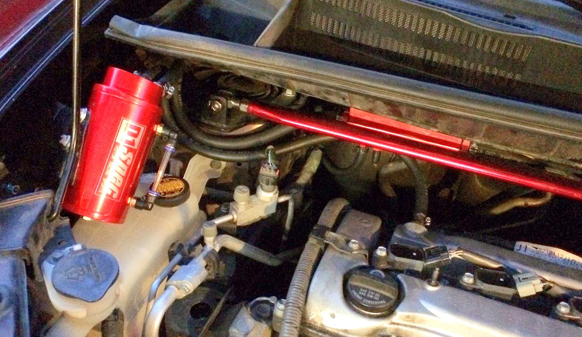
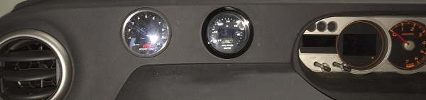
* Wideband and boost/vac gauges running. I picked up a brand new AEM wideband setup on craigslist and then end up going with a APSX vacuum/boost gauge, which turned out to be crap. I've since switched to a simple glowshift digital vacuum/boost gauge, but I don't have an updated picture on hand. Here are the gauges with the old APSX one in place:
* I'm running an automatic transmission, so I installed a transmission cooler to help with the expected load increase. I'm still running traditional fluid, so I'll probably switch to full synthetic once the supercharger is up and running:
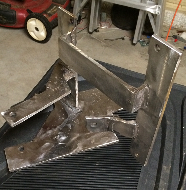
* Supercharger mounting bracket fabrication has been started. It's about 75% finished, but there is still a lot of grinding, welding, and bracing to do. The unit will sit just above the header (yes, I have a strategy for heat) and has plenty of room between the unit and the hood for air pipes. This is 1/4" mild steel, and I will mount two idler pulleys to the side to handle belt routing (I'll double up and go 1/2" near the mountings; lots more on that later).
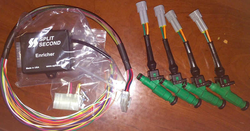
* Split-second enricher is installed, but I'm waiting on the fuel injectors (I'm waiting until the S/C is mounted to do this last). I will be using 440cc injectors (green giants lathed to fit with plug adapters; a cheap alternative to deatschwerks) to handle increased fuel demand in open loop, and the split second enricher will handle closed loop enrichment under boost. This is my entire management strategy, and I don't think anything else will be needed. I do have the ability to do the TRD supercharger flash at home to pull some timing if needed, but I don't think it will be.
Next Steps (in no particular order):
* Replace stock header with turbo log style header and fabricate new downpipe (needed for clearance and proper heat shielding). This is also part of my "failure" strategy if I can't make the project work and I have to fall back to a turbo; the alternative would be a more compact standard header that would have to be replaced in that scenario.
* Finishing the mounting bracket
* Running intake piping (needed the intercooler and mounting bracket done for this)
* Installing the air bypass valve (looking at a Bosch OEM unit for price and reliability)
* Finishing the pulley hub
* Installing the fuel injectors
These units are absolutely ideal because they are:
1. Incredibly cheap
The reason they are cheap is that they used a special clutched 3.75" pulley that has no aftermarket support, so no one wants to mess with them. It may turn out that having a 7th groove added to the original pulley (it's a 6 groove unit) would be the best option, since that's about the right size pulley for our belt setup. I'm starting with a 3.85" modular edelbrock pulley, and making a custom adapter hub is still one of the big to-do items. I'll know in the end if the original was in fact the correct size (the math suggests so).
2. Properly sized for our engine
The M62 is designed for engines in the 2.0 to 4.0 liter range, and they are very efficient (compared to centrifugal superchargers) at low pressure (I'm aiming for around 5.5 PSI) at reasonably low RPM range. I was originally looking a the Eaton M45, but the M62 can be spun much slower and provide the same output.
3. Reliable
These are OEM units that are designed and sold for long term OEM operation. Not only are they likely to last longer, but rebuilds and rebuilt units can often be had for a fraction of the cost of the rebuild or replacement of a turbo.
4. Upgradeable
A roots style supercharger provides a very linear increase in airflow which can be adjusted dramatically by changing the pulley size. This is very different from a turbocharger in that there isn't really a complex compressor map; it's basically a straight line. In theory, the M62 could provide over 14 PSI intercooled with a smaller pulley, which is way beyond what the stock engine (and probably transmission) can handle.
Progress:
* The intercooler is in (solid mounted to the front crash bar). I used a $60 eBay unit and I'm actually really happy with the quality. I drilled holes from the bottom of the crash bar and dropped bolts in from the middle (there's an empty space in the middle back of the bar for this), so it's very firmly mounted by all three lugs; I can actually grab the intercooler and shake the car with it and it won't budge.
* Vacuum block installed. This is a $33 eBay unit; the quality of the block is really good, though the connections are pretty soft aluminum and the o-rings are kind of weak. I've been using it for about a month with no leaks.
* Catch can installed and routed (routing will change once I have the S/C piping setup). This is a $28 eBay unit that needed some work. I opened it up, attached a tube with some holes in it that runs to the bottom of the can, and filled it with stainless steel wool (the standard method for turning a cheap catch can into a respectable unit). I also resealed all connections with black permatex to prevent any possible leaks. I've been using this for about a month with no problems, though I haven't yet worked out a quick drain solution.
* Wideband and boost/vac gauges running. I picked up a brand new AEM wideband setup on craigslist and then end up going with a APSX vacuum/boost gauge, which turned out to be crap. I've since switched to a simple glowshift digital vacuum/boost gauge, but I don't have an updated picture on hand. Here are the gauges with the old APSX one in place:
* I'm running an automatic transmission, so I installed a transmission cooler to help with the expected load increase. I'm still running traditional fluid, so I'll probably switch to full synthetic once the supercharger is up and running:
* Supercharger mounting bracket fabrication has been started. It's about 75% finished, but there is still a lot of grinding, welding, and bracing to do. The unit will sit just above the header (yes, I have a strategy for heat) and has plenty of room between the unit and the hood for air pipes. This is 1/4" mild steel, and I will mount two idler pulleys to the side to handle belt routing (I'll double up and go 1/2" near the mountings; lots more on that later).
* Split-second enricher is installed, but I'm waiting on the fuel injectors (I'm waiting until the S/C is mounted to do this last). I will be using 440cc injectors (green giants lathed to fit with plug adapters; a cheap alternative to deatschwerks) to handle increased fuel demand in open loop, and the split second enricher will handle closed loop enrichment under boost. This is my entire management strategy, and I don't think anything else will be needed. I do have the ability to do the TRD supercharger flash at home to pull some timing if needed, but I don't think it will be.
Next Steps (in no particular order):
* Replace stock header with turbo log style header and fabricate new downpipe (needed for clearance and proper heat shielding). This is also part of my "failure" strategy if I can't make the project work and I have to fall back to a turbo; the alternative would be a more compact standard header that would have to be replaced in that scenario.
* Finishing the mounting bracket
* Running intake piping (needed the intercooler and mounting bracket done for this)
* Installing the air bypass valve (looking at a Bosch OEM unit for price and reliability)
* Finishing the pulley hub
* Installing the fuel injectors
Last edited by k1114; 07-23-2015 at 04:00 AM.
 05-04-2015, 06:57 PM
#3
Senior Member
SL Member
Thread Starter
Join Date: Aug 2009
Posts: 120
Added more information and a photo for management (SSE and injectors).
I'm looking into installing the split second enricher sometime in the next couple days; it doesn't really do anything unless it sees boost, so there shouldn't be any harm in getting the install out of the way.
I'm looking into installing the split second enricher sometime in the next couple days; it doesn't really do anything unless it sees boost, so there shouldn't be any harm in getting the install out of the way.
05-05-2015, 03:50 PM
#4
The bracket doesn't look bad at all Paul. I don't know why, but I thought your S/C was an M45 this whole time. I'm sure you will get your set-up done before me but it's going to be interesting to see the differences once they are both done.
05-05-2015, 07:47 PM
#5
Senior Member
SL Member
Thread Starter
Join Date: Aug 2009
Posts: 120
Our builds will definitely be a lot different. I originally started with the idea of trying to do this on a way that others could duplicate, but everything is starting to become very custom, which is honestly a bit disappointing (though not surprising). I'm still aiming for cheap and easy components where possible.
I got the wiring harness for the split second enricher cleaned up and I'm going to set up the mounting bracket for it tonight I think. It turns out that after the combined and bridged connections there are actually only three wires (power, ground, and in-line O2 sensor tap) and I should be able to tap all of those right near the ECU. I'll need to run a long vacuum line since my distribution block is on the opposite side of the engine bay, but that shouldn't be a big deal. I just need to find the ECU pinout now.
Edit: found the pinout; had it in my notes (different car but should be the same): http://share.qclt.com/%E4%B8%B0%E7%9...tem/005007.pdf
Last edited by k1114; 05-05-2015 at 10:44 PM.
05-06-2015, 02:00 AM
#6
Senior Member
SL Member
Thread Starter
Join Date: Aug 2009
Posts: 120
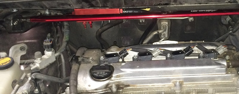
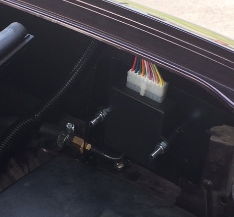
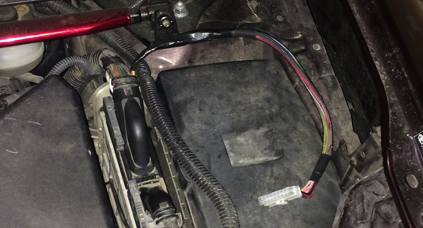
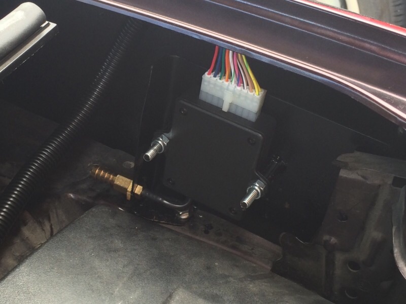
Edit: got the wiring harness in place for the SSE; just needs some loom and appropriate zip ties, and then I'll start on the actual mounting bracket for the module. Here's a pic of the harness in my incredibly dirty engine bay:
Here's how to wire it:
1. Yellow with green stripe wire goes to B30-112 (AFR+)
2. Red wire goes to B30-108 (12v ignition switched)
3. Black and tan with black stripe wires go to B30-46 (Ground)
4. Blue wire is connected to green with yellow stripe wire (does not connect to car; just jumper one wire to another on the SSE harness)
I know there's a lot of them, but the rest of the wires are unused.
Last edited by k1114; 05-06-2015 at 05:00 AM.
05-06-2015, 06:23 PM
#7
Senior Member
SL Member
Thread Starter
Join Date: Aug 2009
Posts: 120
I tested out the SSE and it works beautifully; pressure on the vac line or flipping the test switch results in an immediate drop of AFR to 12.7 (not the final AFR; just how I have it set for testing).
I'm going to try to finish the mount tonight, but the wire has been cleaned up and loomed.
I'm going to try to finish the mount tonight, but the wire has been cleaned up and loomed.
 05-10-2015, 04:32 AM
#10
Senior Member
SL Member
Thread Starter
Join Date: Aug 2009
Posts: 120
All the bits and pieces to make the new header are on the way. I'm looking forward to all the welding  I'm using a cast iron turbo header and fabricating the down tube from there. This accomplishes three things:
1. Gives enough clearance for the supercharger
2. Allows me to switch to a turbo without rebuying parts if the supercharger doesn't work out.
3. Removes the pre-cat, which should make up for the flow restriction of the new cast manifold.
I'm also looking at setting up some hood struts. The hood prop is kind of in the way of the area where the coolant tank and catch can are, and I want to rework those (I hate the current positioning of both) so making as much room as possible will be helpful.
I'm using a cast iron turbo header and fabricating the down tube from there. This accomplishes three things:1. Gives enough clearance for the supercharger
2. Allows me to switch to a turbo without rebuying parts if the supercharger doesn't work out.
3. Removes the pre-cat, which should make up for the flow restriction of the new cast manifold.
I'm also looking at setting up some hood struts. The hood prop is kind of in the way of the area where the coolant tank and catch can are, and I want to rework those (I hate the current positioning of both) so making as much room as possible will be helpful.
Last edited by k1114; 05-10-2015 at 10:39 PM.
05-11-2015, 07:01 PM
#11
The fun of waiting on parts. I'm waiting for the intake manifold flange, oval runners, and oval velocity stacks I ordered to come in so I can start with fabricating the new intake manifold. Getting close to time to assemble the spare block on my work bench.
05-13-2015, 05:48 PM
#12
Senior Member
SL Member
Thread Starter
Join Date: Aug 2009
Posts: 120
Cast iron header arrived and it provides exactly the clearance I need. I had to grind down the bottom left corner a touch for clearance, but it only took a minute on the bench grinder to take care of. Not sure what (if anything) to coat or paint it with - I love the cast look but I know it will rust fairly quickly. I'm also not sure if I should do any grinding/smoothing to help cut down the weight a little (this thing weighs as much as a small child)
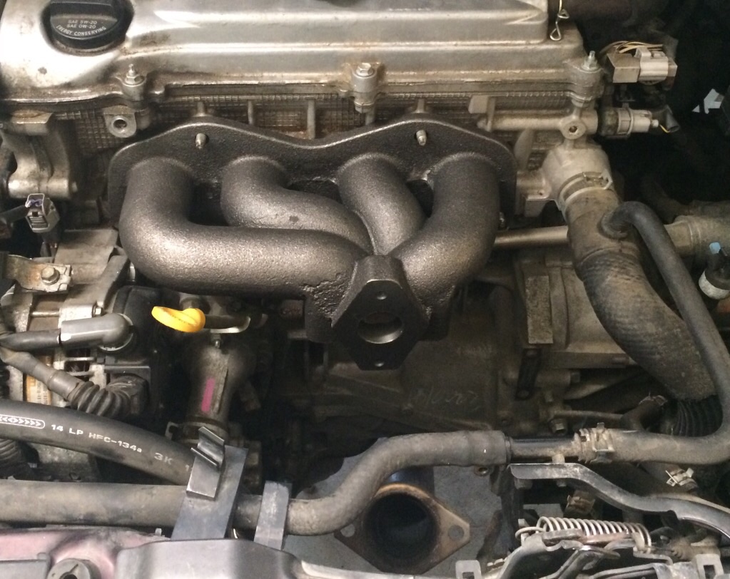
Most of the parts for the down tube arrive tomorrow, so I probably won't mess with going any further tonight.
Most of the parts for the down tube arrive tomorrow, so I probably won't mess with going any further tonight.
05-13-2015, 08:51 PM
#14
Senior Member
SL Member
Thread Starter
Join Date: Aug 2009
Posts: 120
Yep and that's exactly what I was going for; I even looked into buying and gutting the hybrid manifold but decided against it due to the mess and hassle. This way I have a lot of flexibility in design and routing.
A few more parts showed up later in the day, but i still need quite a few to get moving.
A few more parts showed up later in the day, but i still need quite a few to get moving.
05-13-2015, 09:53 PM
#15
Know the feeling. My intake flange, oval runner stock, and oval velocity stacks were just dropped off by UPS. Now I have the basics to see how long I need to make the runners and what space I have to work with for the manifold. I think I'll get off my butt and make a thread of my own as well.
Last edited by Greg S; 05-13-2015 at 10:21 PM.
05-16-2015, 04:07 AM
#16
Senior Member
SL Member
Thread Starter
Join Date: Aug 2009
Posts: 120
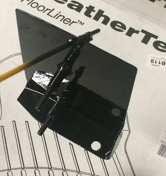
I welded together a scrap jig to make my new header pipe with. I took the stock header and bolted it down to a 1/4" steel sheet (you can't see from this angle but there are three studs for the header) and then bolted up some 1/8" angle steel to the bottom downpipe flange. I poorly welded that all together, put the stock header back in the car, and now I have a jig to relax and make the new header pipe on.
The shiny adapter part is a T3 to 3" adapter; not sure how I feel about the quality, but it's probably ok. Trying to decide if I want straight 3" down to a 2.5" reducer at the collector flange, or adapt to a 2.5" right away... probably won't matter much since the T3 flange hole is so tiny anyway.
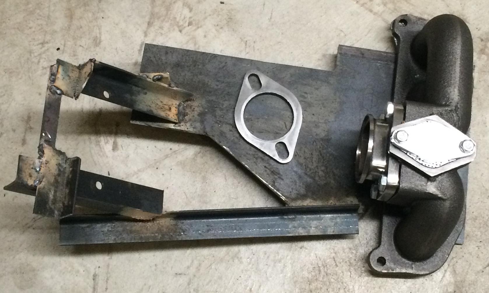
The shiny adapter part is a T3 to 3" adapter; not sure how I feel about the quality, but it's probably ok. Trying to decide if I want straight 3" down to a 2.5" reducer at the collector flange, or adapt to a 2.5" right away... probably won't matter much since the T3 flange hole is so tiny anyway.
Last edited by k1114; 05-16-2015 at 05:42 AM.
05-16-2015, 06:15 PM
#17
I would say adapt it right away. If you're going to have the restriction might as well have it at the beginning. Either that or swap the flange for one that is 2.5 to start with, like this Flange, Discharge T3/GT 4 Bolt, 2.5" Inner Diameter : atpturbo.com
05-17-2015, 05:36 AM
#18
Senior Member
SL Member
Thread Starter
Join Date: Aug 2009
Posts: 120
That's a discharge flange for after the turbo; I would need an intake/header flange like what you would use when doing a remote mount turbo.
I think what I have will work; I may grind it down to just being a flat flange and then weld the pipe directly to it (fits with a little reshaping)
I think what I have will work; I may grind it down to just being a flat flange and then weld the pipe directly to it (fits with a little reshaping)
05-19-2015, 03:04 AM
#19
Senior Member
SL Member
Thread Starter
Join Date: Aug 2009
Posts: 120
Got a lot of work in on the new downpipe today. I end up using the T3 to 3" adapter and it worked out well. The whole pipe is 3" down to a 2.5" reducer right at the bottom flange. Here's a quick partial shot; note that this has not been cleaned up yet, and flux welding is messy. This is just the top (the bottom is frighteningly messy):
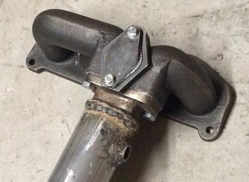
Remaining work on this item:
1. Find a suitable donut gasket; I think 2.5" ID by 3" OD is right
2. Smooth all remaining welds enough that I can stand to look at them (they're bad) and check for leaks
3. Create mounts to replace the support brackets right below the factory pre-cat
4. Begrudgingly clean up everything again as the brackets will have resulted in another world of flux welding mess
5. Paint the whole thing with black header paint
6. (Maybe) wrap the downpipe (not the cast part)
7. Create some kind of side heat shield for where the dipstick and alternator are (nothing fancy)
Last edited by k1114; 05-19-2015 at 03:16 AM.
05-24-2015, 02:06 PM
#20
Senior Member
SL Member
Thread Starter
Join Date: Aug 2009
Posts: 120
Project is briefly on hold; clicking and popping from my front suspension is driving me crazy, so I ordered axles, ball joints, and tie rod ends; going to replace all of those over the next week or two.
I'm also having a really annoying metallic grinding from the head at idle - could be a minor thing or could be time to have the head replaced/rebuilt; going to investigate that a bit more.
In the mean time I'm still working on the exhaust stuff, but no major forced induction parts for a couple weeks while I get this done.