Prius map light mod, plus entry lighting
 06-13-2013, 11:02 PM
#1
Junior Member
Thread Starter

Join Date: Jun 2013
Location: Oklahoma
Posts: 5
Ok so this isn't a completely new interior modification but I've completed it with my only little additions. Thanks to user Bamboo on ClubXB for the initial write up.
I'm going to use his write up and pictures to explain the installation but expand upon it to modify the light itself to include entry lighting. This way not only will you be able to use the map light feature any time like originally designed, but the lights will turn on then dim just like the original XB dome light does once the doors are open/closed or the key fob is pressed.
Here is the original write up (my additions and wiring modifications can be found in the second post)
http://www.clubxb.com/forums/showthread.php?t=48900
We all know the 1st gen Scion xB is severely lacking when it comes to usable and practical internal lighting. Our one dome light is not sufficient enough to light the front of the cabin thoroughly no matter how many LEDs you squish in there. Hence, map lights and overhead console solutions.
I would like to make clear that I am not responsible for any damage, mistakes, dismembering, or any other thing that may go wrong with your install should you choose to try this. This is just a guide based on my experience with this particular mod in my car.
I bit the bullet and bought a Toyota Prius map light to install. I saw this picture of someone on Scionlife that achieved an OEM look with their install and I wanted to replicate it for myself. I didn�t really have too much to go on, but my biggest thing for this was I DID NOT want to drop the headliner again to do this install. So keeping that in mind, we begin;
Difficulty: 4 out of 10 (basic wire splicing skills required, basic cutting skills, basic panel removal)
Nerve: 7 out of 10 (The part where you twiddle the Xacto knife in your hand as you stare your headliner)
Total install time (assuming you have all the components and tools you need): ~ 1 hour � 1.5 hours
Tools/materials:
Toyota Prius Dome Light (Model years: 2001-2003, unsure of part number)
Xacto knife
Scissors
Zip Ties
Wire hanger
Wire crimpers
Electrical tape
Butt Connectors/Spade connectors/ringlet connectors (whatever your preference really)
Sheet of paper (for template)
3 sewing pins
18 gauge wire (I used about 10 feet and I�ll explain why� this can vary depending on where you hook up your power and ground)
GAME TIME!!!
So I bought the map light from ebay for $35. Painted it black to match my interior and here it is ready to go. This is the map light from the 2001-2003 Toyota Prius. Other model years look different and are very different sizes so keep it in mind. Also the bulbs for these lights are a kind I�ve never seen before nor could I find a part number for them. I�m not LED handy, so I don�t know how one would change them to LEDs, but I�m leaving mine incandescent because I want them as a practical option to see things and not necessarily as a remote dome light.
 This image has been resized. Click this bar to view the full image. The original image is sized 1024x768.
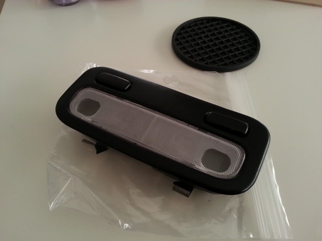
This image has been resized. Click this bar to view the full image. The original image is sized 1024x768.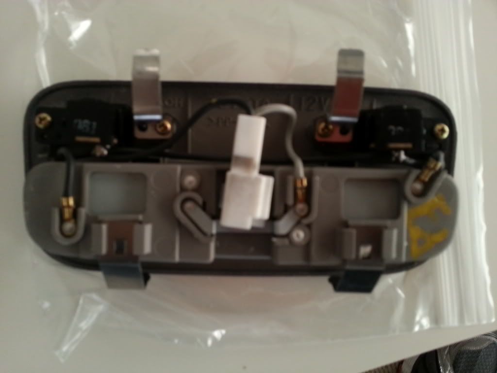
First things first. TEST YOUR LIGHT! You don�t want to go through this whole process and realize your light doesn�t work or your bulbs are messed up or your switches don�t work. Connect some wires to the positive and negative points on the back of the light and touch the wires to the correct nodes of your battery. On my Prius light, the power line was the light gray wires and my ground were the black. Push your switches to the on position (depressed) and see if it light up on contact. Assuming this works, your light is fine and lets move on.
Alright, time to make a template for the hole you will need to make. Get your paper and scissors. DO NOT MAKE THE TEMPLATE THE SIZE OF THE COVER OF THE LIGHT (the front face of it). MAKE THE TEMPLATE SIZE BASED ON WHAT PART NEEDS TO GO IN YOUR HEADLINER (the back portion)!!! Here�s a pic of the back of the light and I�ve outlined where approximately you should be measuring for you template.
This image has been resized. Click this bar to view the full image. The original image is sized 1024x768.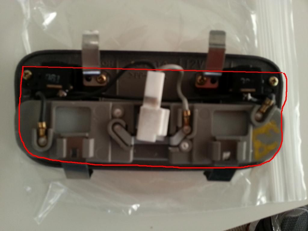
MAJOR TIP: You can always cut more away if the hole ends up being too small. Be conservative. Make the template slightly smaller that the hole would need to be. Then you can widen it later for the perfect fit.
Ok you have a template now. Congratulations. You�ve cut out a shape like a five year old. LOL
Now time to mount up the template in the correct spot. I used 3 sewing pins to affix the template to the headliner. TAKE YOUR TIME MEASURING! Measure once, twice, ten times. You only have one headliner. Get another person to look and see if it looks straight.
This image has been resized. Click this bar to view the full image. The original image is sized 1024x768.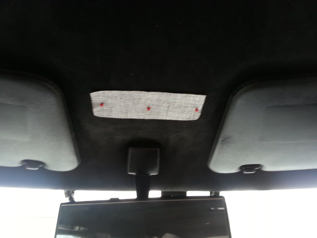
Now time to muster up your nerve and not pee yourself. Get your Xacto knife (or very sharp cutting implement) and CAREFULLY AND SLOWLY CUT AROUND YOUR TEMPLATE. I suggest continually poking the headliner with the sharp tip of the Xacto knife instead of pulling across to cut. This way you don�t pull the headliner and you get a cleaner cut. There is nothing behind that area except empty space so don�t worry about cutting any wires or anything.
This image has been resized. Click this bar to view the full image. The original image is sized 1024x768.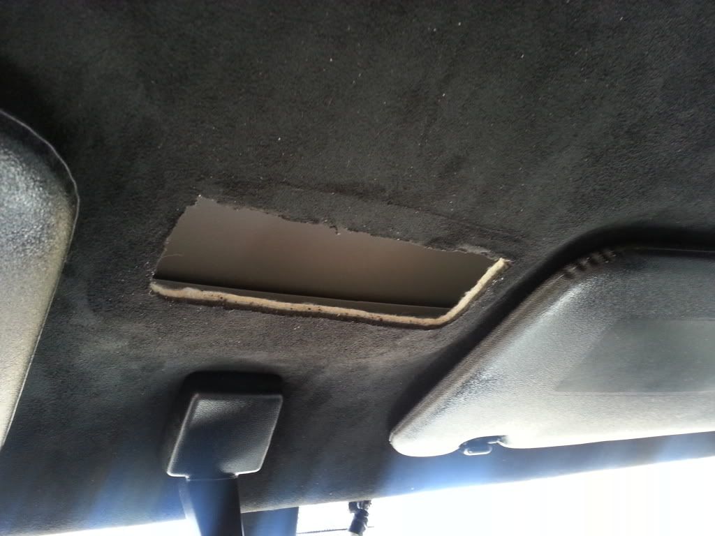
Time to run the wires. I attempted to use the extended wire hanger from the OEM dome light spot (for those that don�t know this trick, take a wire hangar and undo it so it is just one long piece of hanger rod. You can push this into spaces to get to other holes you�ve created, attach the wires you wish to run to the tip you�ve pushed through, and pull the hangar back out to you so the wire comes with it.)
My initial thought was to connect the map light power and ground wires to the constant hot and grounds of the dome light. Unfortunately, I could not seem to get the wire hangar through (the downfalls of trying to do this without dropping the headliner). Nor could I see what was stopping it. So plan B was use the same wire hangar trick from the driver�s side A-pillar, pushing it through from the A-pillar side and putting my hand in the hole I created and retrieving the wire hangar. Here�s a pic of the wire hangar through both sides with my wires taped to the wire hangar end(kind of hard to see, sorry)
This image has been resized. Click this bar to view the full image. The original image is sized 1024x768.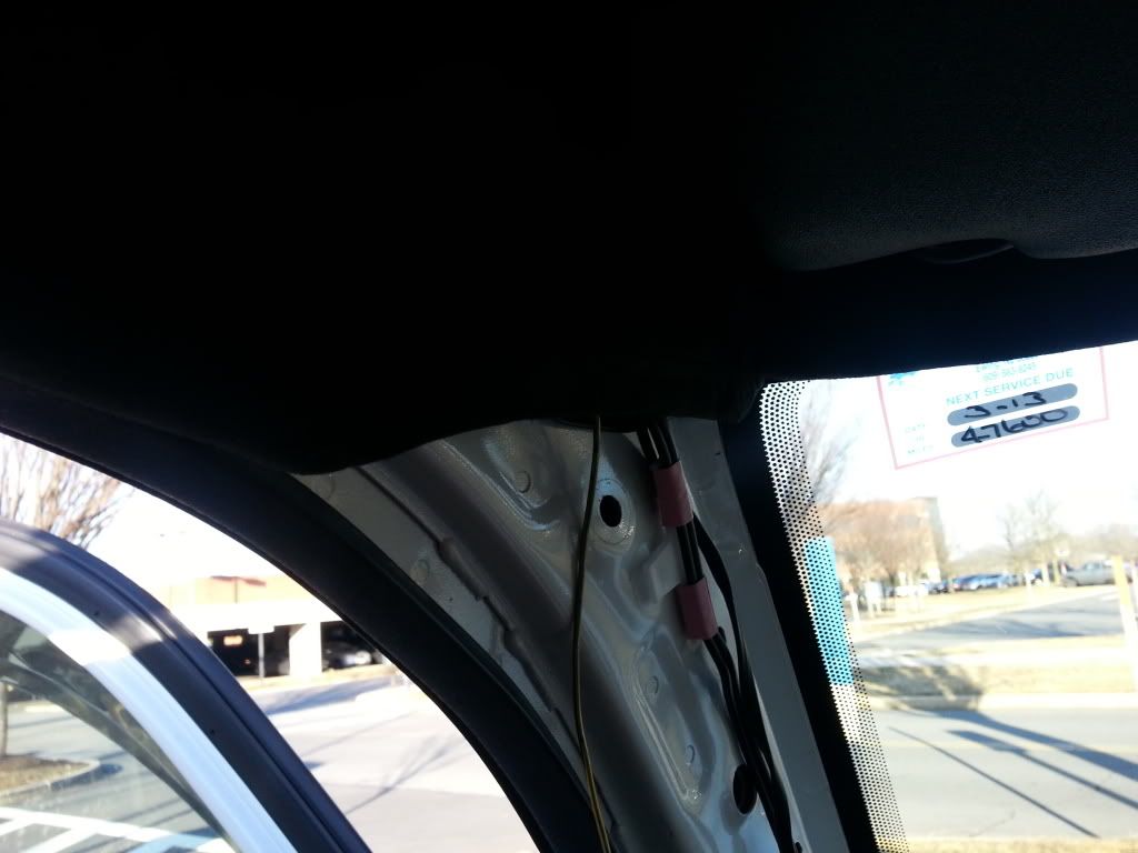
This image has been resized. Click this bar to view the full image. The original image is sized 1024x768.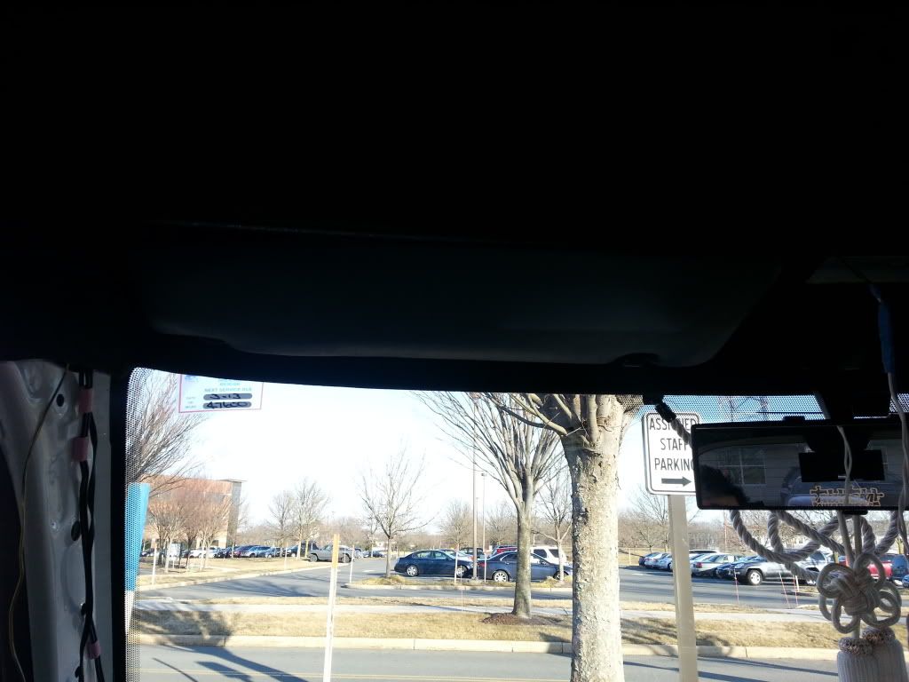
This image has been resized. Click this bar to view the full image. The original image is sized 1024x768.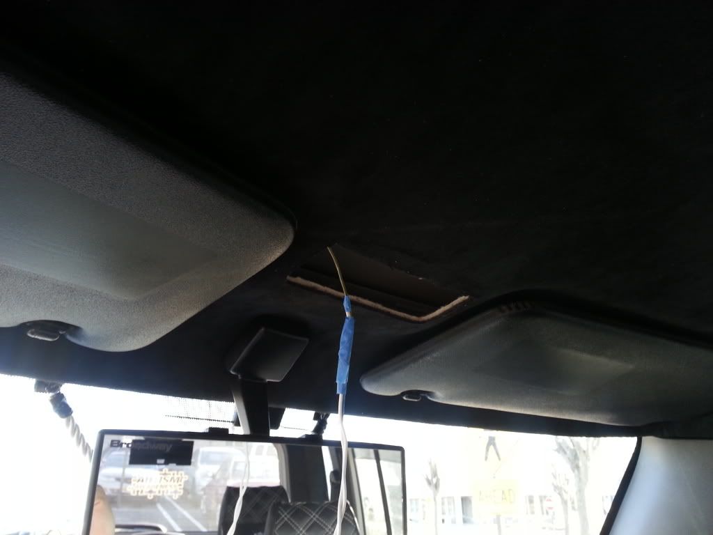
Simply put, after the wire is attached to end you managed through, pull back through to the A pillar and voila! You have wire. Then I ran the wire down to the internal fuse box area by the driver�s feet. Zip tie the wire for cleanliness. Popped the panel off in front of the fuse box and put my hand in there to retrieve the wires from the top of the dash (lots of space)
This image has been resized. Click this bar to view the full image. The original image is sized 768x1024.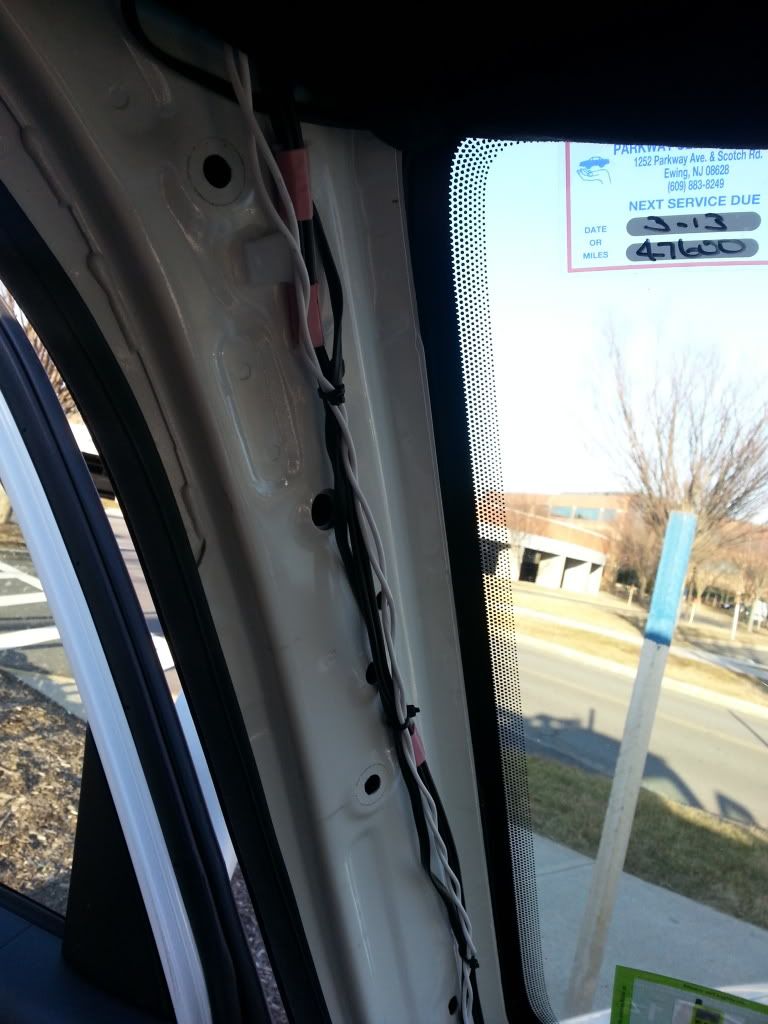
This image has been resized. Click this bar to view the full image. The original image is sized 768x1024.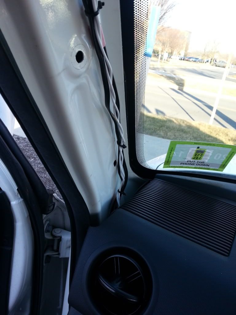
Don�t connect your power and ground yet. Save it for later.
Ok now back up to the hole in your roof. I ended up cutting the white connector off the map light because I didn�t care to find the OEM connector for the light at a junkyard and it didn�t come with it when I bought the light. I spliced spade connectors to the ends of my wires from my light as well as the wires hanging from my roof.
This image has been resized. Click this bar to view the full image. The original image is sized 768x1024.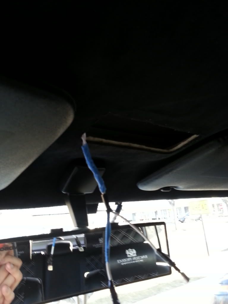
Now time to consider how the light mounts. I used the piece that I cut out as a measuring tool for the metal claws on the light. I made a diagram to begin the explanation.
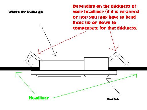
The headliner itself plus the metal claws on the light will hold the light firmly in place. The trick is to make sure that the hole you made is a tight fit for the light and to bend the metal clips so the gap between the end of the claw and the lip of the light is the same thickness as your headliner. Look at the diagram as an example.
Connect your spade connectors together from your map light and the wire harness you made that�s hanging from your roof. Electrical tape them individually so power and ground spades do not touch, then electrical tape both together so it is less cumbersome.
Time to push the light up into your roof. Hook the claws at the top of the light (where the switches are) into the hole first because the bottom is what we need to press into the headliner (based on the claw design, you�ll see the difference). Push gently but firmly (that�s what she said� x1) and you may need to widen the hole slightly if it isn't big enough (x2 haha) and if you get the right fit in the hole, it should sit snugly in place (x3 lol). No one said you had to be mature here...
This image has been resized. Click this bar to view the full image. The original image is sized 1024x768.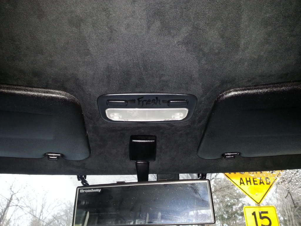
Here is where you can do whatever you want as far as where you connect your power and ground to. There are a bazillion places you can ground your setup to around the fuse box area, and quite a few places you can splice your power to (or run it through the engine grommet to the battery. Wire up a fuse inline if you do it this way just in case. That�s what I did and why I needed so much wire, different solutions require different amounts, so better to have more than less in this case).
After connecting up the power and ground, test your light and well done! You have a maplight.
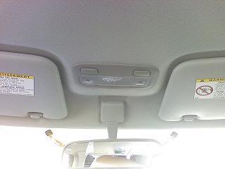
Here�s mine all finished up. I spy my goober self in the mirror in one of the pics hahaha
This image has been resized. Click this bar to view the full image. The original image is sized 1024x768.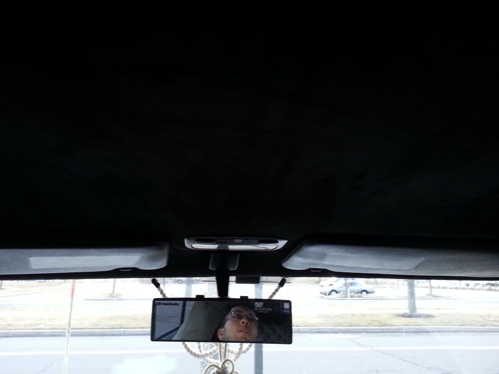
This image has been resized. Click this bar to view the full image. The original image is sized 1024x768.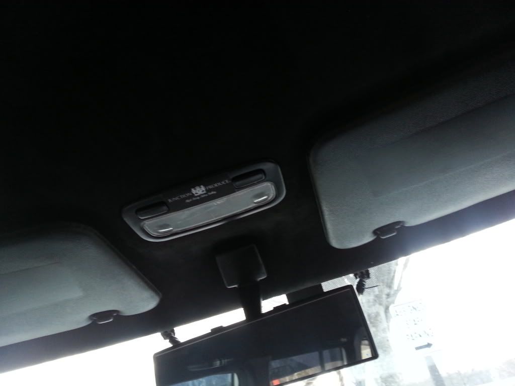
This image has been resized. Click this bar to view the full image. The original image is sized 1024x768.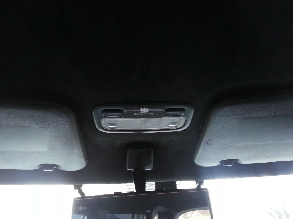
This image has been resized. Click this bar to view the full image. The original image is sized 1024x768.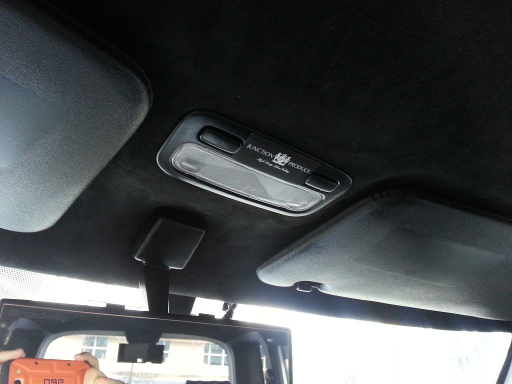
I hope this helps you guys. I�m always trying to give back to the forums that help me so much!
Be easy peeps.
Rob
I'm going to use his write up and pictures to explain the installation but expand upon it to modify the light itself to include entry lighting. This way not only will you be able to use the map light feature any time like originally designed, but the lights will turn on then dim just like the original XB dome light does once the doors are open/closed or the key fob is pressed.
Here is the original write up (my additions and wiring modifications can be found in the second post)
http://www.clubxb.com/forums/showthread.php?t=48900
We all know the 1st gen Scion xB is severely lacking when it comes to usable and practical internal lighting. Our one dome light is not sufficient enough to light the front of the cabin thoroughly no matter how many LEDs you squish in there. Hence, map lights and overhead console solutions.
I would like to make clear that I am not responsible for any damage, mistakes, dismembering, or any other thing that may go wrong with your install should you choose to try this. This is just a guide based on my experience with this particular mod in my car.
I bit the bullet and bought a Toyota Prius map light to install. I saw this picture of someone on Scionlife that achieved an OEM look with their install and I wanted to replicate it for myself. I didn�t really have too much to go on, but my biggest thing for this was I DID NOT want to drop the headliner again to do this install. So keeping that in mind, we begin;
Difficulty: 4 out of 10 (basic wire splicing skills required, basic cutting skills, basic panel removal)
Nerve: 7 out of 10 (The part where you twiddle the Xacto knife in your hand as you stare your headliner)
Total install time (assuming you have all the components and tools you need): ~ 1 hour � 1.5 hours
Tools/materials:
Toyota Prius Dome Light (Model years: 2001-2003, unsure of part number)
Xacto knife
Scissors
Zip Ties
Wire hanger
Wire crimpers
Electrical tape
Butt Connectors/Spade connectors/ringlet connectors (whatever your preference really)
Sheet of paper (for template)
3 sewing pins
18 gauge wire (I used about 10 feet and I�ll explain why� this can vary depending on where you hook up your power and ground)
GAME TIME!!!
So I bought the map light from ebay for $35. Painted it black to match my interior and here it is ready to go. This is the map light from the 2001-2003 Toyota Prius. Other model years look different and are very different sizes so keep it in mind. Also the bulbs for these lights are a kind I�ve never seen before nor could I find a part number for them. I�m not LED handy, so I don�t know how one would change them to LEDs, but I�m leaving mine incandescent because I want them as a practical option to see things and not necessarily as a remote dome light.
This image has been resized. Click this bar to view the full image. The original image is sized 1024x768.This image has been resized. Click this bar to view the full image. The original image is sized 1024x768.First things first. TEST YOUR LIGHT! You don�t want to go through this whole process and realize your light doesn�t work or your bulbs are messed up or your switches don�t work. Connect some wires to the positive and negative points on the back of the light and touch the wires to the correct nodes of your battery. On my Prius light, the power line was the light gray wires and my ground were the black. Push your switches to the on position (depressed) and see if it light up on contact. Assuming this works, your light is fine and lets move on.
Alright, time to make a template for the hole you will need to make. Get your paper and scissors. DO NOT MAKE THE TEMPLATE THE SIZE OF THE COVER OF THE LIGHT (the front face of it). MAKE THE TEMPLATE SIZE BASED ON WHAT PART NEEDS TO GO IN YOUR HEADLINER (the back portion)!!! Here�s a pic of the back of the light and I�ve outlined where approximately you should be measuring for you template.
This image has been resized. Click this bar to view the full image. The original image is sized 1024x768.MAJOR TIP: You can always cut more away if the hole ends up being too small. Be conservative. Make the template slightly smaller that the hole would need to be. Then you can widen it later for the perfect fit.
Ok you have a template now. Congratulations. You�ve cut out a shape like a five year old. LOL
Now time to mount up the template in the correct spot. I used 3 sewing pins to affix the template to the headliner. TAKE YOUR TIME MEASURING! Measure once, twice, ten times. You only have one headliner. Get another person to look and see if it looks straight.
This image has been resized. Click this bar to view the full image. The original image is sized 1024x768.Now time to muster up your nerve and not pee yourself. Get your Xacto knife (or very sharp cutting implement) and CAREFULLY AND SLOWLY CUT AROUND YOUR TEMPLATE. I suggest continually poking the headliner with the sharp tip of the Xacto knife instead of pulling across to cut. This way you don�t pull the headliner and you get a cleaner cut. There is nothing behind that area except empty space so don�t worry about cutting any wires or anything.
This image has been resized. Click this bar to view the full image. The original image is sized 1024x768.Time to run the wires. I attempted to use the extended wire hanger from the OEM dome light spot (for those that don�t know this trick, take a wire hangar and undo it so it is just one long piece of hanger rod. You can push this into spaces to get to other holes you�ve created, attach the wires you wish to run to the tip you�ve pushed through, and pull the hangar back out to you so the wire comes with it.)
My initial thought was to connect the map light power and ground wires to the constant hot and grounds of the dome light. Unfortunately, I could not seem to get the wire hangar through (the downfalls of trying to do this without dropping the headliner). Nor could I see what was stopping it. So plan B was use the same wire hangar trick from the driver�s side A-pillar, pushing it through from the A-pillar side and putting my hand in the hole I created and retrieving the wire hangar. Here�s a pic of the wire hangar through both sides with my wires taped to the wire hangar end(kind of hard to see, sorry)
This image has been resized. Click this bar to view the full image. The original image is sized 1024x768.This image has been resized. Click this bar to view the full image. The original image is sized 1024x768.This image has been resized. Click this bar to view the full image. The original image is sized 1024x768.Simply put, after the wire is attached to end you managed through, pull back through to the A pillar and voila! You have wire. Then I ran the wire down to the internal fuse box area by the driver�s feet. Zip tie the wire for cleanliness. Popped the panel off in front of the fuse box and put my hand in there to retrieve the wires from the top of the dash (lots of space)
This image has been resized. Click this bar to view the full image. The original image is sized 768x1024.This image has been resized. Click this bar to view the full image. The original image is sized 768x1024.Don�t connect your power and ground yet. Save it for later.
Ok now back up to the hole in your roof. I ended up cutting the white connector off the map light because I didn�t care to find the OEM connector for the light at a junkyard and it didn�t come with it when I bought the light. I spliced spade connectors to the ends of my wires from my light as well as the wires hanging from my roof.
This image has been resized. Click this bar to view the full image. The original image is sized 768x1024.Now time to consider how the light mounts. I used the piece that I cut out as a measuring tool for the metal claws on the light. I made a diagram to begin the explanation.
The headliner itself plus the metal claws on the light will hold the light firmly in place. The trick is to make sure that the hole you made is a tight fit for the light and to bend the metal clips so the gap between the end of the claw and the lip of the light is the same thickness as your headliner. Look at the diagram as an example.
Connect your spade connectors together from your map light and the wire harness you made that�s hanging from your roof. Electrical tape them individually so power and ground spades do not touch, then electrical tape both together so it is less cumbersome.
Time to push the light up into your roof. Hook the claws at the top of the light (where the switches are) into the hole first because the bottom is what we need to press into the headliner (based on the claw design, you�ll see the difference). Push gently but firmly (that�s what she said� x1) and you may need to widen the hole slightly if it isn't big enough (x2 haha) and if you get the right fit in the hole, it should sit snugly in place (x3 lol). No one said you had to be mature here...
This image has been resized. Click this bar to view the full image. The original image is sized 1024x768.Here is where you can do whatever you want as far as where you connect your power and ground to. There are a bazillion places you can ground your setup to around the fuse box area, and quite a few places you can splice your power to (or run it through the engine grommet to the battery. Wire up a fuse inline if you do it this way just in case. That�s what I did and why I needed so much wire, different solutions require different amounts, so better to have more than less in this case).
After connecting up the power and ground, test your light and well done! You have a maplight.
Here�s mine all finished up. I spy my goober self in the mirror in one of the pics hahaha
This image has been resized. Click this bar to view the full image. The original image is sized 1024x768.This image has been resized. Click this bar to view the full image. The original image is sized 1024x768.This image has been resized. Click this bar to view the full image. The original image is sized 1024x768.This image has been resized. Click this bar to view the full image. The original image is sized 1024x768.I hope this helps you guys. I�m always trying to give back to the forums that help me so much!
Be easy peeps.
Rob
 06-13-2013, 11:43 PM
#2
Junior Member
Thread Starter
Join Date: Jun 2013
Location: Oklahoma
Posts: 5
Here is where things get different between my installation and Bamboo's.
Unlike him I was able to fish wires from my new hole to the original light's hole. I worked from the new hole back instead of the old hole forward. Not sure if this is why I was able to feed it through or if I just got lucky? Anyways keep at it since it can be done, just go slow and have some patience.

Once those are fed through through its time to modify the light a bit. You can accomplish this with crimp slices or tap splices, but I chose to solder. If you choose to solder do as much as you can outside the car and be careful of burns. I do suggest the use of spade
If you choose to solder do as much as you can outside the car and be careful of burns. I do suggest the use of spade connectors in some places so that you can unplug the light if need be.

First off you need to remove the white two pin male plug from the prius light. You can cut it off it you like but I de-pinned the plug because I wanted to save as much of the wire length as I could.

Next using solder, a splice or a wire tap connect your newly run wires to the existing overhead light wiring insuring that the battery is disconnected or the other end of your wires if capped and insulated. Be sure to label which wire is which for later.
In my 2006 the Blue/Yellow wire was my 12V constant and the Brown/Yellow wire was the switched ground that operates via the door switches.
BLUE/YELLOW 12V+ CONSTANT
BROWN/YELLOW SWITCHED GND
On the Prius light itself you need to attach the Grey wire to your 12V+ CONSTANT
The SWITCHED GND should be spliced into the wires running from each light socket terminal to the bottom post of the left and right switch.
This will cause the lights to come on just as a normal overhead light would. They should power off once the doors are closed and the Dimmer's timed circuit has opened.
To insure that you can use the map light feature you need to run a Constant ground to the black wire that you removed from the plug. This is the black wire that runs between the two posts of the left and right switched up to the black wire in the plug. I accomplished this using a third wire run from the original light to the new light. At the original end use a ring terminal placed under one of the screws to provide CONSTANT GND, then simple splice or solder the other end to the black wire on your new light.
[img]http://d114hh0cykhyb0.cloudfront.net/images/uploads/NRT-2218-led-installation-supply-store.jpg[img]
Here is a quick diagram of how the wiring should now be

Here's a picture showing the top and bottom posts on the switches

Then simply finish the installation according to Bamboo's writeup and reconnect your battery if disconnected.I will try to take some more pictures tomorrow of the wiring and installation to better clarify things. If you have any questions
Unlike him I was able to fish wires from my new hole to the original light's hole. I worked from the new hole back instead of the old hole forward. Not sure if this is why I was able to feed it through or if I just got lucky? Anyways keep at it since it can be done, just go slow and have some patience.
Once those are fed through through its time to modify the light a bit. You can accomplish this with crimp slices or tap splices, but I chose to solder. If you choose to solder do as much as you can outside the car and be careful of burns. I do suggest the use of spade
If you choose to solder do as much as you can outside the car and be careful of burns. I do suggest the use of spade connectors in some places so that you can unplug the light if need be.
First off you need to remove the white two pin male plug from the prius light. You can cut it off it you like but I de-pinned the plug because I wanted to save as much of the wire length as I could.
Next using solder, a splice or a wire tap connect your newly run wires to the existing overhead light wiring insuring that the battery is disconnected or the other end of your wires if capped and insulated. Be sure to label which wire is which for later.
In my 2006 the Blue/Yellow wire was my 12V constant and the Brown/Yellow wire was the switched ground that operates via the door switches.
BLUE/YELLOW 12V+ CONSTANT
BROWN/YELLOW SWITCHED GND
On the Prius light itself you need to attach the Grey wire to your 12V+ CONSTANT
The SWITCHED GND should be spliced into the wires running from each light socket terminal to the bottom post of the left and right switch.
This will cause the lights to come on just as a normal overhead light would. They should power off once the doors are closed and the Dimmer's timed circuit has opened.
To insure that you can use the map light feature you need to run a Constant ground to the black wire that you removed from the plug. This is the black wire that runs between the two posts of the left and right switched up to the black wire in the plug. I accomplished this using a third wire run from the original light to the new light. At the original end use a ring terminal placed under one of the screws to provide CONSTANT GND, then simple splice or solder the other end to the black wire on your new light.
[img]http://d114hh0cykhyb0.cloudfront.net/images/uploads/NRT-2218-led-installation-supply-store.jpg[img]
Here is a quick diagram of how the wiring should now be
Here's a picture showing the top and bottom posts on the switches
Then simply finish the installation according to Bamboo's writeup and reconnect your battery if disconnected.I will try to take some more pictures tomorrow of the wiring and installation to better clarify things. If you have any questions

Thread
Thread Starter
Forum
Replies
Last Post
SkillFreeJake
Scion tC 2G Aero & Exterior
17
07-27-2015 12:34 AM
Besk_one
Scion xA/xB 1st-Gen ICE & Interior
6
11-17-2003 09:28 PM