
How to remove / solder a PLCC LED for gauge / hvac work PICS


Another question I get asked all the time "What method do you use to remove or solder on a tiny plcc leds?" Well this is how I do it and how all of my swaps are done. If any other swappers have any input or advice, feel free to post! Happy to have your knowledge as well.
Tools required
- A good 15-25w soldering iron or variable unit.
- .032 lead free solder
- tweezers
- Small stiff brush
- rubbing alcohol
- q-tips
- Patience & a bottle of JD "for after haha"
Start off by letting your iron come up to temp. Once up to temp, use the tip of the iron to heat and lift the edge of the led.


Next use your tweezers to lift the led while you heat the 2nd contact. The led should lift right off of the board.

Once the led is remove, apply a small amount of solder to each contact. Do NOT go overboard here. A little goes a long ways!

Next, use your tweezers to hold the new led and press it down on the board while heating the edge of the solder. The solder will melt and bond with the metal on the led. If you make a brush like stroke with the iron while the solder is hot, the solder joint will look and be flawless.
Only thing to be VERY carefull about here is to NOT overheat the led or melt it.

Once a single side of the led is held in place, use your tweezers to press down on the other side while you heat the solder. Use the same method to solder this side of the led. Keep holding the led down until the solder becomes solid.

This step is VERY important. Once both sides of the led are soldered in place, go back to the first side you soldered and heat the solder back up and you may hear a faint "click" that is taking away stress from the first solder joint that bent slightly while soldering on and pressing down on joint number 2. If you do not perform this step, the led may break itself loose over a long period of time and very hot weather

Use the stiff brush and alcohol to remove any flux leftover from solder, use a q-tip to help clean it up if needed. A good quality lead free solder & iron at the proper temp should leave little flux on the board.
Below are some random photos of solder work on my customers swaps. If your joints look like this, then you are doing great!
Now all of this sounds easy that you have mastered 1 led. Now go forth and finish the other 50+ of them hahaha! You will know why led swappers do not do work for free. Very tedious and very time consuming to do it all right.
Example 1, OEM solder joints.

Examples 2+ My solder work.


Tools required
- A good 15-25w soldering iron or variable unit.
- .032 lead free solder
- tweezers
- Small stiff brush
- rubbing alcohol
- q-tips
- Patience & a bottle of JD "for after haha"
Start off by letting your iron come up to temp. Once up to temp, use the tip of the iron to heat and lift the edge of the led.
Next use your tweezers to lift the led while you heat the 2nd contact. The led should lift right off of the board.
Once the led is remove, apply a small amount of solder to each contact. Do NOT go overboard here. A little goes a long ways!
Next, use your tweezers to hold the new led and press it down on the board while heating the edge of the solder. The solder will melt and bond with the metal on the led. If you make a brush like stroke with the iron while the solder is hot, the solder joint will look and be flawless.
Only thing to be VERY carefull about here is to NOT overheat the led or melt it.
Once a single side of the led is held in place, use your tweezers to press down on the other side while you heat the solder. Use the same method to solder this side of the led. Keep holding the led down until the solder becomes solid.
This step is VERY important. Once both sides of the led are soldered in place, go back to the first side you soldered and heat the solder back up and you may hear a faint "click" that is taking away stress from the first solder joint that bent slightly while soldering on and pressing down on joint number 2. If you do not perform this step, the led may break itself loose over a long period of time and very hot weather
Use the stiff brush and alcohol to remove any flux leftover from solder, use a q-tip to help clean it up if needed. A good quality lead free solder & iron at the proper temp should leave little flux on the board.
Below are some random photos of solder work on my customers swaps. If your joints look like this, then you are doing great!
Now all of this sounds easy that you have mastered 1 led. Now go forth and finish the other 50+ of them hahaha! You will know why led swappers do not do work for free. Very tedious and very time consuming to do it all right.
Example 1, OEM solder joints.
Examples 2+ My solder work.


Senior Member


SoCal tC Club
SL Member
Team N.V.S.
Scinergy
Scion Evolution
Joined: Oct 2004
Posts: 15,699
looks good!
hmm.. for fully pushing down on the leds.. i perfer not to use tweezers but my own fingers for complete full control..
yes.. my fingers come millimeters away from a hot soldering iron.... lol.. i'm used to it.... i don't think i have much feeling in my fingers much... but i do grow my fingernails slightly to help.
also, i like to remove as much solder as possible.. and at least to one side... and when adding solder back to the pad, just do the other side. it'll help in having the led flush with the board.... so solder in the led with that side... push down as i do the second side (adding solder).. and continue to push down while redoing the first side.
voila!
oh and jeremy? what method do you use to remove the 1206 sized leds and resistors? if it's the same way i do it, then well
HERE'S A VIDEO!!
clicky-->> Desoldering/Soldering Small SMD LEDs
video found on http://www.llamma.com/xbox360/mods/x...%20mount%20led


Senior Member
Scikotics
SL Member
Joined: Nov 2004
Posts: 9,731
From: Minneapolis, MN
Thanks for putting this up jeremy. I tried to explain this some in some of my writeups, but have never put any pics to go with it. This should make it easier to understand.
Also good that you mentioned adding new solder. The flux in the old solder is gone (flux is what cleans the connection and makes for a good, long lasting one), so new solder should always be used to put the new components on. I actually just remove all of the old solder with solder wick after removing all of the old leds and then start over with new. Just makes it easier to keep from adding too much when I put the new solder down.
Now, if you do the leds first, then you are ready for the resistors... and then the leds on the head unit... THEN a bottle of captain (sorry, I will let you drink the JD jeremy ! )
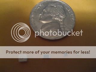
For reference though, here are pics of the plcc-2, the 1206 resistors for the 05-06, the 0805s for the 07-08 and finally, the leds for the head unit!
Also good that you mentioned adding new solder. The flux in the old solder is gone (flux is what cleans the connection and makes for a good, long lasting one), so new solder should always be used to put the new components on. I actually just remove all of the old solder with solder wick after removing all of the old leds and then start over with new. Just makes it easier to keep from adding too much when I put the new solder down.
Now, if you do the leds first, then you are ready for the resistors... and then the leds on the head unit... THEN a bottle of captain (sorry, I will let you drink the JD jeremy ! )
For reference though, here are pics of the plcc-2, the 1206 resistors for the 05-06, the 0805s for the 07-08 and finally, the leds for the head unit!
hahaha yeah, I love that pic, Good to show all 4. I have a pic like that with a plcc and an 0603 sitting on an quarter on my site trying to show how really small this stuff is. I was not going to do a writeup for the 0603's but I did shot a pic of an 0805 in the pic above. I find most noobs end up wreaking havok on anything smaller than an 0805  25w non temp controlled radioshack irons do not cut it on 0805 and smaller leds *LOL*
Originally Posted by SquallLHeart
looks good!
hmm.. for fully pushing down on the leds.. i perfer not to use tweezers but my own fingers for complete full control..
yes.. my fingers come millimeters away from a hot soldering iron.... lol.. i'm used to it.... i don't think i have much feeling in my fingers much... but i do grow my fingernails slightly to help.
also, i like to remove as much solder as possible.. and at least to one side... and when adding solder back to the pad, just do the other side. it'll help in having the led flush with the board.... so solder in the led with that side... push down as i do the second side (adding solder).. and continue to push down while redoing the first side.
voila!
oh and jeremy? what method do you use to remove the 1206 sized leds and resistors? if it's the same way i do it, then well
HERE'S A VIDEO!!
clicky-->> Desoldering/Soldering Small SMD LEDs
video found on http://www.llamma.com/xbox360/mods/x...%20mount%20led
hmm.. for fully pushing down on the leds.. i perfer not to use tweezers but my own fingers for complete full control..
yes.. my fingers come millimeters away from a hot soldering iron.... lol.. i'm used to it.... i don't think i have much feeling in my fingers much... but i do grow my fingernails slightly to help.
also, i like to remove as much solder as possible.. and at least to one side... and when adding solder back to the pad, just do the other side. it'll help in having the led flush with the board.... so solder in the led with that side... push down as i do the second side (adding solder).. and continue to push down while redoing the first side.
voila!
oh and jeremy? what method do you use to remove the 1206 sized leds and resistors? if it's the same way i do it, then well
HERE'S A VIDEO!!
clicky-->> Desoldering/Soldering Small SMD LEDs
video found on http://www.llamma.com/xbox360/mods/x...%20mount%20led
*LOL* Yeah I do not use tweezers either to remove the leds, I just grab them and touch the other side to remove. With practice burns are very few and far between.
I found the most killer pair of spring loaded tweezers that have become my right arm for placing leds or resistors. They grab an led or resistor and hold like no tommorow. They work on any size. You can set them down and they still grip whatever they grap with no damage.
Senior Member
Scikotics
SL Member
Joined: Nov 2004
Posts: 9,731
From: Minneapolis, MN
Not at all. That is why I have a weller temp controlled iron!
For those that dont know the difference, here is how they work.
A power controlled iron (like one rated 25W) controlls the current to the element, which, since it is at a known resistance, controls the power, thus the heat output. The problem is that over time, if the resistance of the element begins to drop (or raise), the iron is now producing more or less heat than it used to. Not a good thing. It also doesnt account for soldering large items, which wick away heat quickly, or small items, which do not.
A temp controlled iron has a sensor in the tip that actually measures temp and keeps it steady, regardless of everything else. As you start working with smaller devices or soldering IC's, like processors, a power controlled iron is not a safe thing to use. The other side is that most temp controlled irons are ESD (electro static discharge) shielded. And on any part of these boards, static is a BAD thing. CMOS and static do not get along
Senior Member
Scikotics
SL Member
Joined: Nov 2004
Posts: 9,731
From: Minneapolis, MN
I remove the 0603's just like I do the others really. The difference is that the whole led heats up and just sticks to the iron, so I just knock it off quickly in the parts bin
I do the same with the 0603's as the plcc's but they do not melt on me at 260f. Also yeah I use a ESD safe iron / rework station with hot air for ic's and smoke filter sucker. Man it saves my lungs when solding so much.
And do you guys have a parts bin with about 40K old leds *LOL* My wife always asks when I am going to empty it. Has grown to be quite large and full haha!
And do you guys have a parts bin with about 40K old leds *LOL* My wife always asks when I am going to empty it. Has grown to be quite large and full haha!
Senior Member
Scikotics
SL Member
Joined: Nov 2004
Posts: 9,731
From: Minneapolis, MN
I have little parts bags filled with all sorts of leds :D
And you dont even want to know how many amber leds I have have I have no idea why I still have them.. but it is cool to see the pile grow larger!
I also run lower temp on the 0603s. If you tin the tip well and heat them the led will stay with the little blob of solder and you can just scrape em off before they get too hot and melt.
Now, if you really want fun, hand solder a 144 pin flat pack processor... and get out the giant magnifying glass when you do it !
And you dont even want to know how many amber leds I have have
I also run lower temp on the 0603s. If you tin the tip well and heat them the led will stay with the little blob of solder and you can just scrape em off before they get too hot and melt.
Now, if you really want fun, hand solder a 144 pin flat pack processor... and get out the giant magnifying glass when you do it !


Senior Member
SL Member
Joined: Mar 2006
Posts: 524
From: Where you can't find
Clean!!! I don't have a thin head solder like you do. mine is larger because it is being worned out. Each time I solder leds, I always have big puddles of lead right next to the leds. Using large soldering head to swap leds like the ones in the HU is a pain in the a$$
Senior Member
Scikotics
SL Member
Joined: Nov 2004
Posts: 9,731
From: Minneapolis, MN
Definitely get yourself a smaller tip. Also, use solder very sparingly. My solder info and tips writeup here goes into detail on the actual soldering piece as well... which reminds me.. I need to put that up with my other writeups on the scionwiki as well!