Quick and Dirty H.I.D. FAQ For N00bs


 05-15-2006, 02:05 AM
#22
Senior Member
SL Member

Join Date: Apr 2005
Location: Philly/Wilmington
Posts: 893
DIY harness would be nice, im working on one atm.... well im doing the research part
since ack154 asked for one... maybe i can try.. i looked at hidplanet.com's forums and i really think they suck.. They are tech geeks who write for geeks. they dont' really think about the audiences who would be reading... them :T
i know.. how about maximus gives us some pointers
since ack154 asked for one... maybe i can try.. i looked at hidplanet.com's forums and i really think they suck.. They are tech geeks who write for geeks. they dont' really think about the audiences who would be reading... them :T
i know.. how about maximus gives us some pointers
05-15-2006, 04:32 PM
#23
Senior Member
SL Member

Join Date: Dec 2004
Location: Bay Area, CA
Posts: 1,227
In the simplest form, you just need to connect 4 wires to a 12v relay. There are 5 pins on a typical relay labeled as 30, 87, 87am 85 and 86.
Connect pin 30 with an inline fuse to +12v of battery
Connect pin 87 with inline fuses to +12v of both ballasts
Connect pin 85 to +12v of 9006 socket
Connect pin 86 to ground
No use for pin 87a in this situation
This assumes you know how to use a soldering iron, wire crimper, wire stripper, heat shrink tubing, and terminal connectors.
You�ll also need to ground the -12v on both ballast. Some people like to use two relays, one for each side, for added security.
05-15-2006, 04:34 PM
#24
Senior Member
SL Member
Join Date: Dec 2004
Location: Bay Area, CA
Posts: 1,227
here's a more involved DIY
Originally Posted by Ocelaris
Crimpless - Solder joints are a much better connection, acts like a solid piece of wire.
Heatshrink - your best friend for a watertight seal - electrical tape is ok, use it liberally. Heatshrink is also necessary for mechanically stabilizing solder joints. For example when you don't have a proprietary connector; solder wires on, and then heatshrink 4 layers or more on and around the plug so that when the wires are yanked, they pull on the plastic heat shrink tubing not the solder joints.
Relay sockets - so you can replace your relays if they die and the user can actually do it themselves. female 1/4" spade clips are ok, but if you unhook them from the relay, you lose what wire goes where.
No diodes! - unless you are using them for a specific purpose like passing power/ground to low beams from high beams in order to keep lows on while hitting your highs... IMO they are unnecessary. A relay socket replaces the need for a diode across the coil. If Bosch wanted diodes on their relays, they would have specified them. Replace the relay if it dies, don't alter your wiring to possibly extend the life of the relay.
Split loom - makes a nice clean finished appearence the higher the temperature rating, the better.
Silicone sealed relay sockets - to seal out moisture
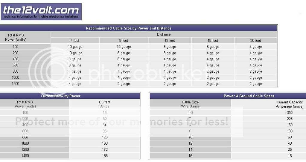
Wire - 14 gauge is about as large a gauge as I personally would use. 16 gauge is also fine for lengths < 6 feet.
OEM male connectors - to attach to stock wiring to get your "triggers" for your relays. SUVLights or Rallylights has them for ~6-8$ a piece. Or you can cut off a bulb, solder wires on, and use heat shrink tubing to mechanically stabilize the socket. see heat shrink tubing.
Hints
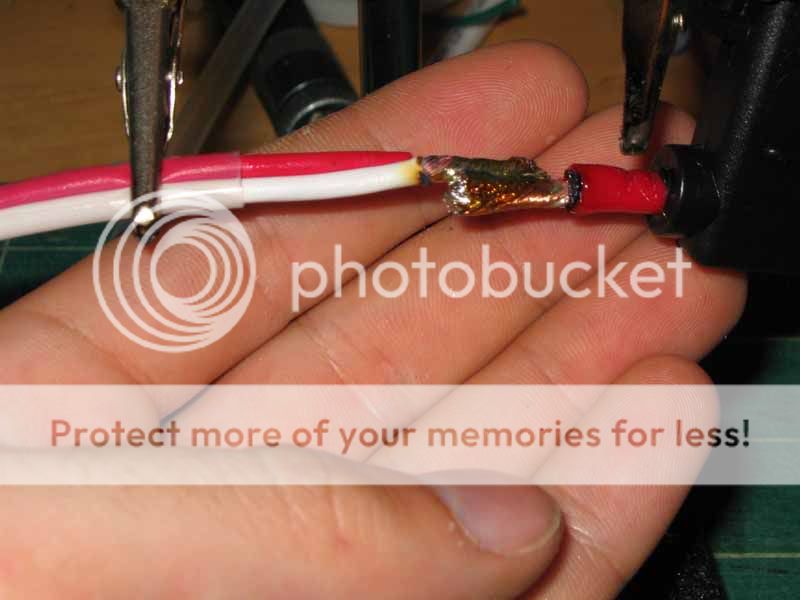
A Butane torch is VERY useful for large solder joints of 3+ wires. Good joints should have the solder flow into the wire so it looks like a wrinkled rasin, not a ripe one!
Some heatshrink tubing is rated at it's final shrink size, and some is rated at it's before shrunk size. There is 2:1 shrink or 3:1 shrink, also there is a dual wall kind where the inner layer melts, oozing out, creating a water proof joint.
Radio shack heatshrink tubing sucks, don't write it off if you've had bad experiences with it.
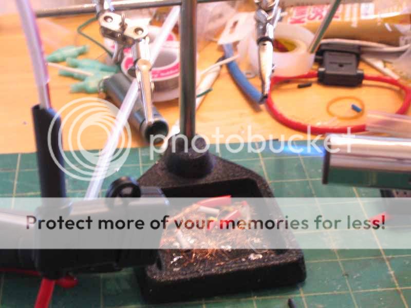
Helping hands are a necessity.
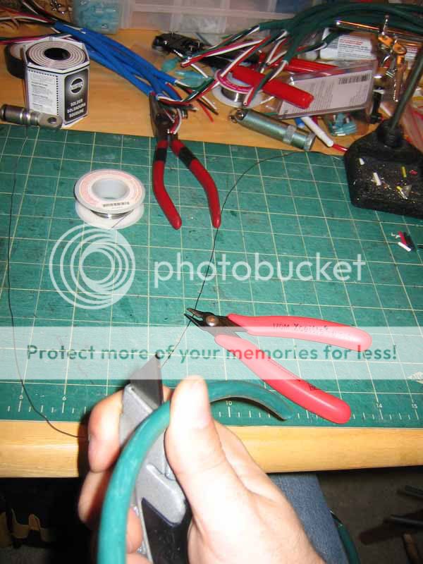
Quick strip tools work great:

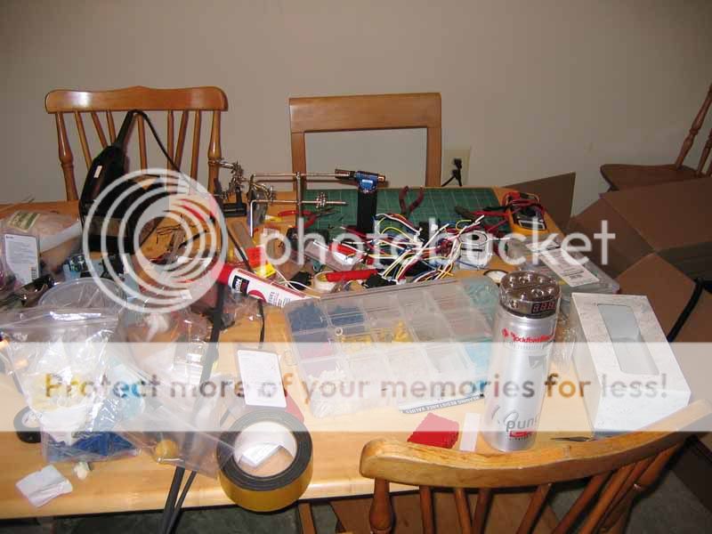
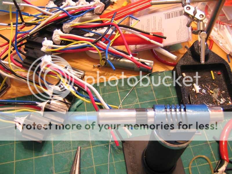
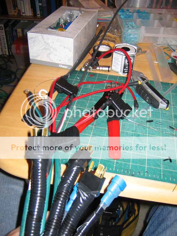
Start with a Messy Table
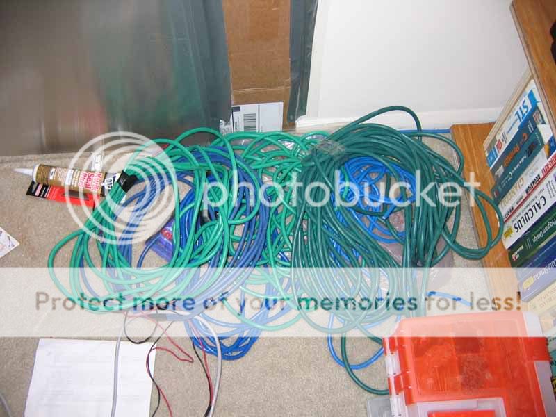
Get LOTS of wire
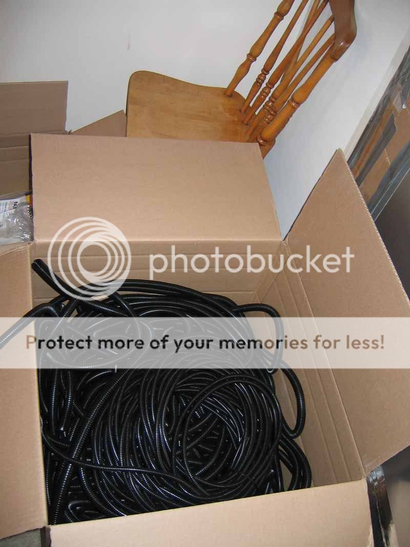
Box of Split Loom
Tons of Cable Ties

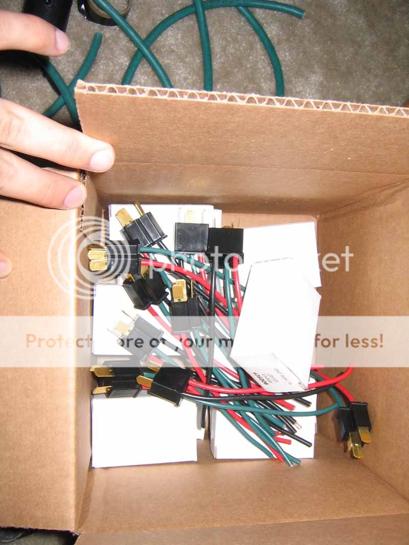
250$ for 30 connectors!!! YIKES!
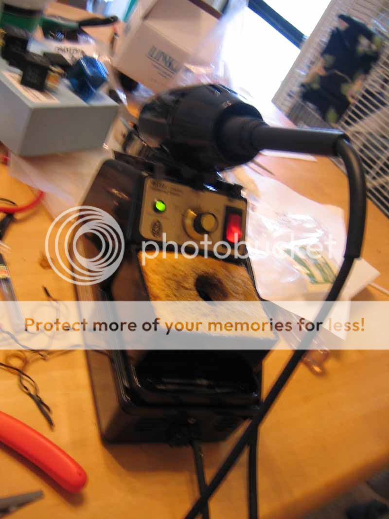
Nice little butane torch for heatshrinking
Soldering Station
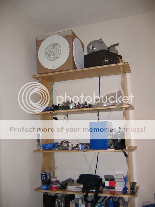
A few tunes via ghetto rigged whole house music... there are 6 sets of speakers throughout the apartment :-0
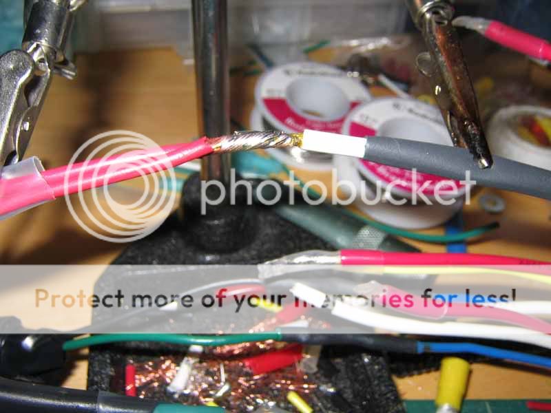
Strip back outter Jacket:
Good solder joints
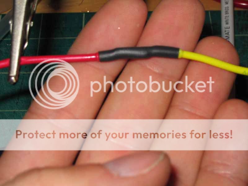
Torchin some heatshrink
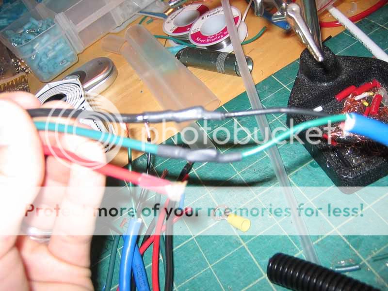
Every joint gets heatshrink
Lots of connectors
You can see this heatshrink tubing has an inner layer which melts, and oozes out to make a water tight seal. This is the good $hit
Unused wires get terminated

Battery Terminal:
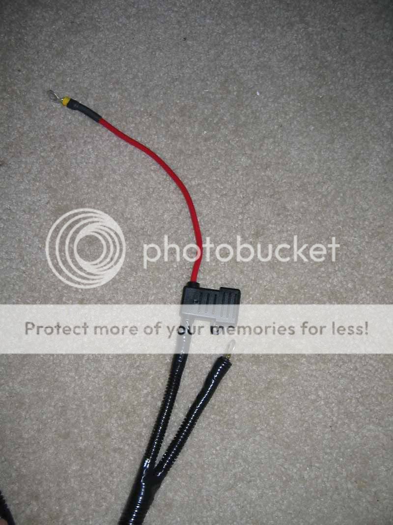
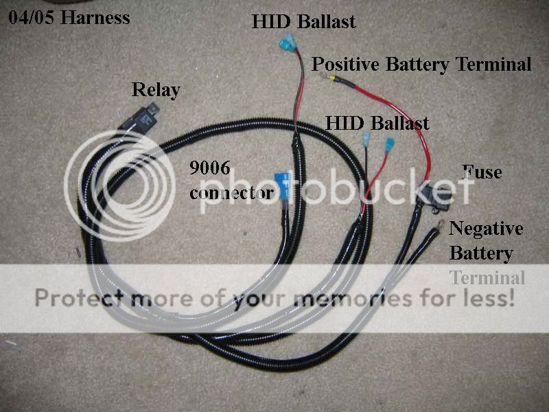
Final Product 9006 for 04/05 harness:
Final Product for H4 02/03 harness:
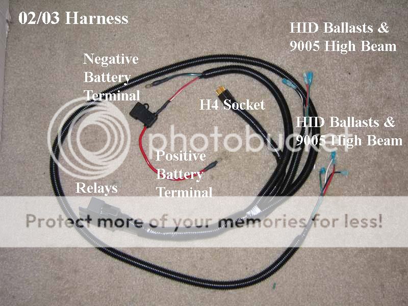
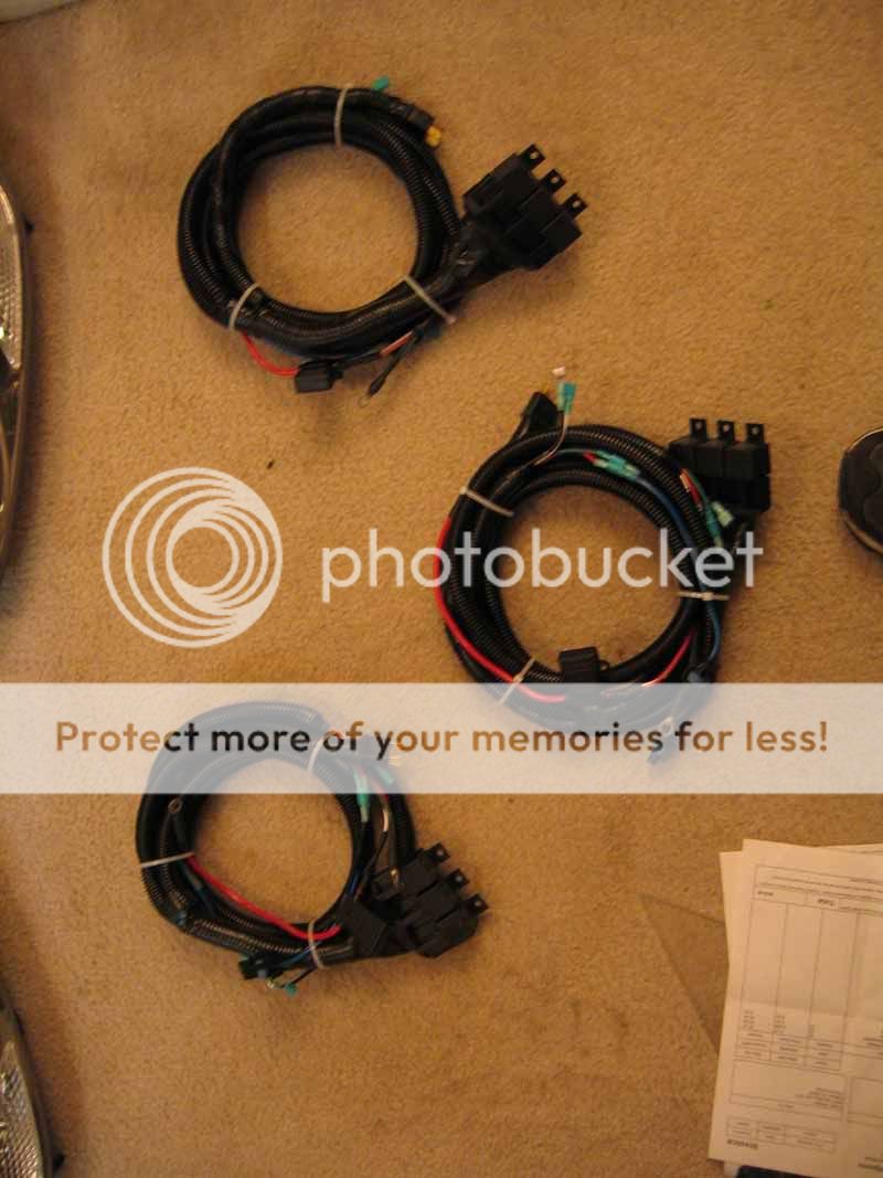
3 completed 02/03 harnesses for ECU EP, TrafficJamsEp, and Psylovibe
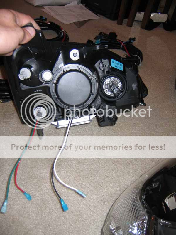
Back of Headlights, quick disconnects soldered and mechanically isolated with 5 layers of heatshrink tubing.
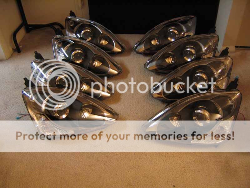
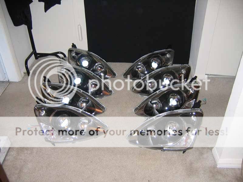
Some cool gratuitious shots of some lovely lights:
Fin
*Update, some diagrams*
9006/9005/H1/H7 or any 2 pin bulb Upgraded Harness:

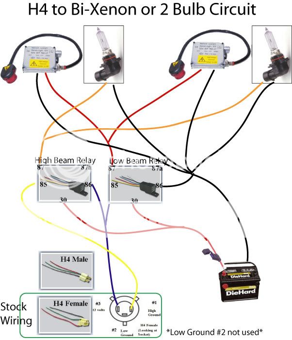
H4 to 9005/9006 (dual filament bulb to 2x single filament bulbs)
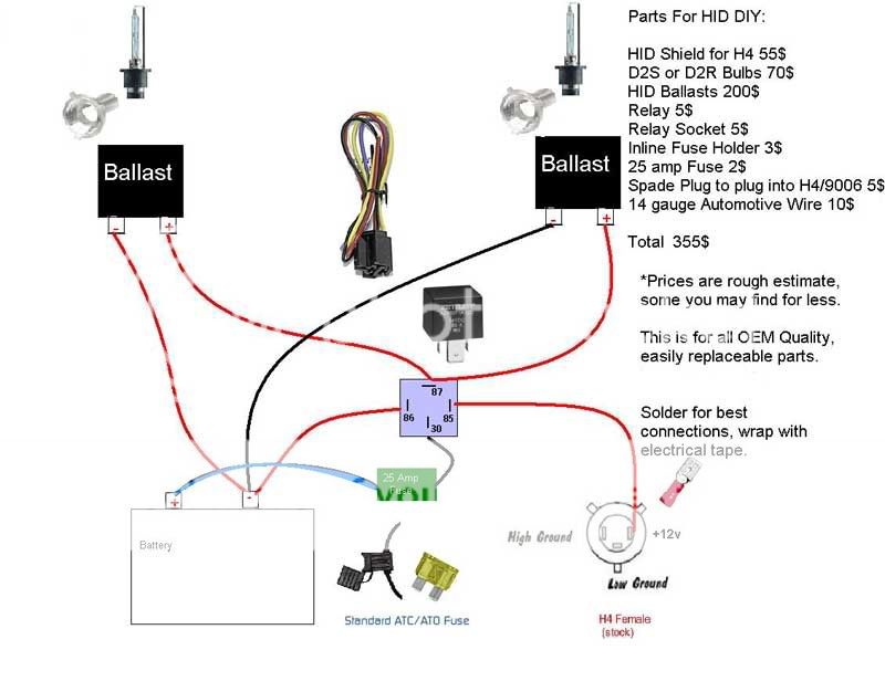
H4 Single Low beam HID Setup:
Many people wanted the low down on crimp vs. Solder... here's my opinion:
Criming is definetly NOT better than soldering. Soldering is definetly NOT better than crimping. Each has a strength and weakness.
My personal preference still is with soldering. I have seen many many crimped joints fail where as I have yet to see a solder joint in a harness fail.
It's impossible to get 4, 12 gauge wires to stick in a crimp terminal, and this is often the requirement when making a harness. For small gauge wire up to 16 gauge, you can probably get up to 3, but forget using a crimp for anything greater than 16 gauge.
I don't use a soldering iron because the gauge wire we use in harnesses makes all but the largest duty soldering irons ineffective. I use a blow torch. It gaurantees you will not have a cold solder joint, and it will wick up to create a much stronger joint than a crimp terminal could ever hope.
However I do use crimp terminals for all quick disconnects, and will continue to do so. I also use them in small quick jobs, and have seen them used appropriately when you don't need to joint multiple wires.
Crimps are quick and easy, and people tend to make more mistakes because of this. Soldering requires alot more concentration, and has the ability to make a much stronger joint.
If you think about crushing metal together versus melting solder, resistance and durability wise, solder wins hands down.
As for gas/water resistance, I use electrical tape. I use TONS of it, I may use half a roll per harness. Solder is cheap, crimp terminals like you suggest can be 0.50$ a piece... like these:

http://www.partsexpress.com/pe/showd...number=095-914
Imagine the price of stocking crimp terminals... it's very expensive and adds to the cost significantly.
Here is the tool that I have:

http://www.partsexpress.com/pe/showd...number=360-642
Ratcheting Crimp terminal with various dies for stamping.
Here is the torch I use for soldering harness joints:

http://www.partsexpress.com/pe/showd...number=372-208
If you're going to do this professionally to make money, it's faster to use crimps. But it is impossible to make good joints with multiple large gauge wire for harnesses like these require. And it creates a greater resistance than a good solder joint makes.
The key is that it depends on the person making the harness. If you're sloppy, it's going to turn out sloppy with either method you use. If you want the best possible connection, solder offers a stronger joint (no arguing that metal is stronger than plastic) and you can make it every bit as water/gas tight with heatshrink that has a melting inner layer, or just wrap the poop out of it with electrical tape which I find to be the easiest and strongest mechanical joint because you can make it as thick as you want.
Good solder joints are stronger, lower resistance, and cheaper than crimp joints. But they do take more time.
Good Crimps are strong, minimal resistance, a tad expensive, but much quicker if you are going to churn out a ton of these.
Each has it's strong points and benefits, and I've made hundreds of harnesses, and I will continue to use solder on all critical joints, and crimps on anything I want quick disconnects for. The readers are welcome to make up their own mind.
Heatshrink - your best friend for a watertight seal - electrical tape is ok, use it liberally. Heatshrink is also necessary for mechanically stabilizing solder joints. For example when you don't have a proprietary connector; solder wires on, and then heatshrink 4 layers or more on and around the plug so that when the wires are yanked, they pull on the plastic heat shrink tubing not the solder joints.
Relay sockets - so you can replace your relays if they die and the user can actually do it themselves. female 1/4" spade clips are ok, but if you unhook them from the relay, you lose what wire goes where.
No diodes! - unless you are using them for a specific purpose like passing power/ground to low beams from high beams in order to keep lows on while hitting your highs... IMO they are unnecessary. A relay socket replaces the need for a diode across the coil. If Bosch wanted diodes on their relays, they would have specified them. Replace the relay if it dies, don't alter your wiring to possibly extend the life of the relay.
Split loom - makes a nice clean finished appearence the higher the temperature rating, the better.
Silicone sealed relay sockets - to seal out moisture
Wire - 14 gauge is about as large a gauge as I personally would use. 16 gauge is also fine for lengths < 6 feet.
OEM male connectors - to attach to stock wiring to get your "triggers" for your relays. SUVLights or Rallylights has them for ~6-8$ a piece. Or you can cut off a bulb, solder wires on, and use heat shrink tubing to mechanically stabilize the socket. see heat shrink tubing.
Hints
A Butane torch is VERY useful for large solder joints of 3+ wires. Good joints should have the solder flow into the wire so it looks like a wrinkled rasin, not a ripe one!
Some heatshrink tubing is rated at it's final shrink size, and some is rated at it's before shrunk size. There is 2:1 shrink or 3:1 shrink, also there is a dual wall kind where the inner layer melts, oozing out, creating a water proof joint.
Radio shack heatshrink tubing sucks, don't write it off if you've had bad experiences with it.
Helping hands are a necessity.
Quick strip tools work great:
Start with a Messy Table
Get LOTS of wire
Box of Split Loom
Tons of Cable Ties
250$ for 30 connectors!!! YIKES!
Nice little butane torch for heatshrinking
Soldering Station
A few tunes via ghetto rigged whole house music... there are 6 sets of speakers throughout the apartment :-0
Strip back outter Jacket:
Good solder joints
Torchin some heatshrink
Every joint gets heatshrink
Lots of connectors
You can see this heatshrink tubing has an inner layer which melts, and oozes out to make a water tight seal. This is the good $hit
Unused wires get terminated
Battery Terminal:
Final Product 9006 for 04/05 harness:
Final Product for H4 02/03 harness:
3 completed 02/03 harnesses for ECU EP, TrafficJamsEp, and Psylovibe
Back of Headlights, quick disconnects soldered and mechanically isolated with 5 layers of heatshrink tubing.
Some cool gratuitious shots of some lovely lights:
Fin
*Update, some diagrams*
9006/9005/H1/H7 or any 2 pin bulb Upgraded Harness:
H4 to 9005/9006 (dual filament bulb to 2x single filament bulbs)
H4 Single Low beam HID Setup:
Many people wanted the low down on crimp vs. Solder... here's my opinion:
Criming is definetly NOT better than soldering. Soldering is definetly NOT better than crimping. Each has a strength and weakness.
My personal preference still is with soldering. I have seen many many crimped joints fail where as I have yet to see a solder joint in a harness fail.
It's impossible to get 4, 12 gauge wires to stick in a crimp terminal, and this is often the requirement when making a harness. For small gauge wire up to 16 gauge, you can probably get up to 3, but forget using a crimp for anything greater than 16 gauge.
I don't use a soldering iron because the gauge wire we use in harnesses makes all but the largest duty soldering irons ineffective. I use a blow torch. It gaurantees you will not have a cold solder joint, and it will wick up to create a much stronger joint than a crimp terminal could ever hope.
However I do use crimp terminals for all quick disconnects, and will continue to do so. I also use them in small quick jobs, and have seen them used appropriately when you don't need to joint multiple wires.
Crimps are quick and easy, and people tend to make more mistakes because of this. Soldering requires alot more concentration, and has the ability to make a much stronger joint.
If you think about crushing metal together versus melting solder, resistance and durability wise, solder wins hands down.
As for gas/water resistance, I use electrical tape. I use TONS of it, I may use half a roll per harness. Solder is cheap, crimp terminals like you suggest can be 0.50$ a piece... like these:
http://www.partsexpress.com/pe/showd...number=095-914
Imagine the price of stocking crimp terminals... it's very expensive and adds to the cost significantly.
Here is the tool that I have:
http://www.partsexpress.com/pe/showd...number=360-642
Ratcheting Crimp terminal with various dies for stamping.
Here is the torch I use for soldering harness joints:
http://www.partsexpress.com/pe/showd...number=372-208
If you're going to do this professionally to make money, it's faster to use crimps. But it is impossible to make good joints with multiple large gauge wire for harnesses like these require. And it creates a greater resistance than a good solder joint makes.
The key is that it depends on the person making the harness. If you're sloppy, it's going to turn out sloppy with either method you use. If you want the best possible connection, solder offers a stronger joint (no arguing that metal is stronger than plastic) and you can make it every bit as water/gas tight with heatshrink that has a melting inner layer, or just wrap the poop out of it with electrical tape which I find to be the easiest and strongest mechanical joint because you can make it as thick as you want.
Good solder joints are stronger, lower resistance, and cheaper than crimp joints. But they do take more time.
Good Crimps are strong, minimal resistance, a tad expensive, but much quicker if you are going to churn out a ton of these.
Each has it's strong points and benefits, and I've made hundreds of harnesses, and I will continue to use solder on all critical joints, and crimps on anything I want quick disconnects for. The readers are welcome to make up their own mind.
 06-10-2006, 02:38 PM
#27
Senior Member
tC squad
SL Member
Team ScioNRG

Join Date: Feb 2006
Location: nEw Ro, NY
Posts: 383
no it doesnt mean that the harnesses arent going to burn out. theres still a good chance of that happening. plug and play means no modification to the wire system just plug stuff in like couple of connectors to the ballast and the aftermarket bulb into the stock socket and poof your done!! Hope this helps
06-23-2006, 02:41 PM
#29
Plug and play can also refer to it being simple and not having to make actual modifications to the housing or existing wiring. Not necessarily just the bulb. Most "kits" are still considered plug and play because you mount what's required and then just PLUG everything in and it's supposed to play. Or at least work.
06-24-2006, 03:39 AM
#30

Ok well heres a thing i want to get the Mc Coullough HID kit just kinda lookin around for prices i want like the 5000 K i think that looks awesome also i got a pocket rocket for Sale ill take a trade for HID ...,. or i got a set of 4 17" gunmetal Motegi MR7s wheels and tires $400 .. lemme know if anyones interested k thanx bye
06-26-2006, 05:37 AM
#31
Junior Member

Join Date: Jun 2006
Posts: 23
As someone who has had 9 different projector retros on different cars and bikes i've owned, HID will not melt your housing. Think about it this way, the stock bulbs run at 55 or 65 watts, HID's run at 35W also HID are more efficient since they dont have a filament. HID's run much cooler than halogen bulbs. So really as long as everything is wired using relays and a fuse there should never be any issues. Also that chart that shows the different temp bulbs is not accurate as has been said before on HIDPlanet
06-27-2006, 12:44 PM
#32
Senior Member
SL Member
Join Date: Apr 2005
Location: Philly/Wilmington
Posts: 893
How about an answer why putting HIDs in your car fry your wiring harness?
Here is a graph to help explain(picture sited itself, please reference to that website! good website)

as you see, the inital start up of the HID light vs Halogen is the amount of amp is way more. The higher the amp, the more heat it generates and eventually wear down your wires until it burns. Yes just a few seconds you may say.... but as time go by, you will risk burning not just your wiring harness, but other wiring components in your car
You can read more here
http://faqlight.carpassion.info/headlamp-harness.html
Here is a graph to help explain(picture sited itself, please reference to that website! good website)
as you see, the inital start up of the HID light vs Halogen is the amount of amp is way more. The higher the amp, the more heat it generates and eventually wear down your wires until it burns. Yes just a few seconds you may say.... but as time go by, you will risk burning not just your wiring harness, but other wiring components in your car
You can read more here
http://faqlight.carpassion.info/headlamp-harness.html
06-28-2006, 05:42 AM
#33
Junior Member
Join Date: Jun 2006
Posts: 23
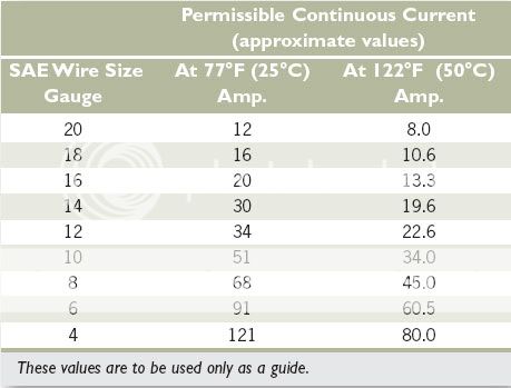
You are right about amps but some of your info about HID's is wrong. OEM HID systems use 35w not 42w, also start up amps is also usually above 20A not 13A like the graph shows. One more gripe is if you look at the wiring to any OEM ballast it is never better than 16g, so if your wires are melting you have other issues that are melting wires
06-28-2006, 01:55 PM
#34
Senior Member
SL Member
Join Date: Apr 2005
Location: Philly/Wilmington
Posts: 893
that is a picture taken from faqlight page, you can read on to it to see why it's 42w, yes it's 35w but 35w is measured from the bulb
different ballast are different, like i said before, this picture is not mines, im using it to set an example.
below is a quote extracted from the website
There is no info on how those numbers were generated in that chart, but the concept should be sufficient to convince car owners to invest in a wiring harness.
i am still learning, but if you still think i am wrong, feel free to point it out and explain, would really appreciate it, espeically from someone like you who have great experience in retrofitting, it's an honor
different ballast are different, like i said before, this picture is not mines, im using it to set an example.
below is a quote extracted from the website
During normal HID operation, you use only 42 watts (35W to run the bulb plus 7W in heat losses in ballast)
i am still learning, but if you still think i am wrong, feel free to point it out and explain, would really appreciate it, espeically from someone like you who have great experience in retrofitting, it's an honor
06-28-2006, 07:22 PM
#35
Junior Member
Join Date: Jun 2006
Posts: 23
Although i have never measured the Watts used at the ballast i can't see it losing 7W to heat loss especially since most of my ballast stay very cool during use. 7W or 16% loss seems an awful lot to me but hey i could be wrong. I am in know way and expert, i just have alot of experience with electronics. But just for fun here are a pics of the labels of different ballasts i have 
A Hella Gen III

Mitsubishi Evolution 8 (Stanley made)

Nissan/Infiniti Q45 (Stanley made)

Toyota/Lexus (Denso Slim Ballast)

Finally a limited run Hella 35/50W output switching ballast

Just thought you guys would be interested in this, by the way you will notice most of the ballasts have output of 35w and 85V, I just figure that if the ballast had a higher input than output it would be noted on the ballast.
A Hella Gen III
Mitsubishi Evolution 8 (Stanley made)
Nissan/Infiniti Q45 (Stanley made)
Toyota/Lexus (Denso Slim Ballast)
Finally a limited run Hella 35/50W output switching ballast
Just thought you guys would be interested in this, by the way you will notice most of the ballasts have output of 35w and 85V, I just figure that if the ballast had a higher input than output it would be noted on the ballast.
06-29-2006, 02:25 PM
#36
Senior Member
SL Member
Join Date: Apr 2005
Location: Philly/Wilmington
Posts: 893
Found something cool that explains why HIDs are blue during startup taken from that FAQ lighting website under the section all about HID bulbs
http://faqlight.carpassion.info/
Note that there is a link on that page to a MS Word document (.doc) the first 2 sections in that document are:
http://faqlight.carpassion.info/
Note that there is a link on that page to a MS Word document (.doc) the first 2 sections in that document are:
Why are HID lights totally blue for a few seconds after startup?
Without going into the physics of electron orbits, photon pumps, valences, and other arcane stuff, it has to do with;
The ballast/igniter, the nature of the arc terminators (cathode -, and anode +), the ignition (startup) current, the vaporizing metallic salts, and the constant Xenon gas fill.
When a cold (room temperature) automotive HID is first turned on, the startup voltage produced by the igniter (sometimes separate, sometimes integrated into the ballast) is in the neighborhood of 20,000-25,000 volts. This high voltage potential forces the current at the arc generating point (cathode -) to leap the gap to the arc receiving point (anode +), identical to what happens with an arc welder. As the �leaping arc� contacts the anode, a number of interesting things start to happen;
1) Light is produced along the arc length, through excitation of the gas molecules of the (constant) Xenon-fill gas. At this point, the arc is quite �fat� and at a very high color (blue) temperature.
2) Robust high temperature blue light is also produced at the anode surface, and (to a lesser extent) at the cathode.
3) This secondary light source (above) is extremely blue (+/- 10,000K), and also semi-spherical in nature, which allows this light source to be reflected by the system�s optics.
4) The arc welder process generates heat, causing the metallic salts also contained in the capsules to begin to vaporize into gas, or gasses. This heating process causes other changes:
5) As the gasses are generated, pressure inside the capsule begins to rise, from a static pressure of 5 atmospheres (from the Xenon fill), to a terminal point of more than 30 atmospheres. Total pressurization takes (typical) 30 seconds to occur.
6) As the pressure increases in the capsule, less voltage is required to sustain the arc (electron flow), and the ignition current is dropped, via the ballast sensing circuitry, in a tapering fashion. This causes the arc to shrink in diameter and stabilize, as well as reduce the electrode surface sources of �blue� light. Note: The electrode (secondary) light sources are now very flat, like an LED, making them difficult to be captured by the reflector surface, because the reflector is designed to reflect axially produced light.
What happens at this point is that the blue light (apparently) goes away. This is because; the arc is shrunken and stabilized, the voltage has been reduced to �arc sustaining�, the fluorescing gasses are running at a lower color temperature, and most of the usable (i.e., by the reflector) light is being generated just along the arc�s axial length. This �sustaining arc� has very little visible blue light, and the flat electrode-generated light is �invisible� to the reflector. Result: No more blue light.
Why some HID lights stay �blue� after warm-up
1) To capture the blue light produced at the arc terminators on a continuous basis, some OEM manufacturers design (deliberately point) a small portion of the reflector to capture the �flat� blue light generated at the anode, and incorporate it as part of the total light output, by design.
2) Other OEMs will just �leave it alone�, knowing that, after a 100 hours or so of �burn time�, the anode will change shape, because of the constant electrical discharge. When this shape change occurs, the anode is no longer ground flat, and the shape of the blue secondary light at the anode changes from a flat, nearly two-dimensional, shape, to something that is three-dimensional. At this time, you have something that the reflector can use, and, you�ve got blue-tinted light, all the time.
3) A trend for �blue� lights has caused several HID capsule makers to �fiddle with� the metallic salt mix just for the aftermarket. By incorporating different metals, specifically Indium, the HID arc can continuously fluoresce at higher color temperatures with the same amount of voltage as used in the �lower color temperature� HID capsules. Results have been mixed, depending on the optics of the final applications. This is due to the �stratified light� nature of the stabilized HID arc, and how the reflector focuses on the total arc �layers�. Also, the use of different metallic salts may also decrease the useful life of the HID capsule, through quicker metal deposition on the capsule walls. Note: Indium is a material also used to plate mirrors, via a cathode/anode process.
-- Produced by Ekooke
 08-05-2006, 03:31 AM
#38
Member
SL Member

Join Date: May 2006
Posts: 77
09-22-2006, 02:27 AM
#40
Senior Member
SL Member

Join Date: Sep 2006
Location: Houston, TX
Posts: 165
Hey, i just installed in a new plug and play Xetronic 6k Hid's, and was thinking about getting fogged out headlights and fogged out rear brake lights. Good idea or bad idea?
If I put in fogged out headlights would it make the light from the bulbs seem less bright??
If I put in fogged out headlights would it make the light from the bulbs seem less bright??