BlackMetal's Nitrous DIY (Updated Pics on Pg. 5 - 02/19/09)
 10-17-2008, 09:24 AM
#1
Senior Member
SL Member
Thread Starter

Join Date: Dec 2007
Location: Des Plaines, IL
Posts: 369
Video on Page 2
Grab a drink or something because there is going to be some good reading for the next few minutes! So let’s get started shall we?
****Disclaimer – This DIY is intended for people that are comfortable working on cars, if you don’t feel comfortable please DO NOT ATTEMPT THIS INSTALLATION on your own – it’s not so simple of an install, take it to a professional! Also, I am in NO WAY responsible for anything you do to YOUR car, or any injuries you or anyone else encounters in the process. This is intended as a helpful guide, not an installation manual to live by – Most important thing is to HAVE FUN!****
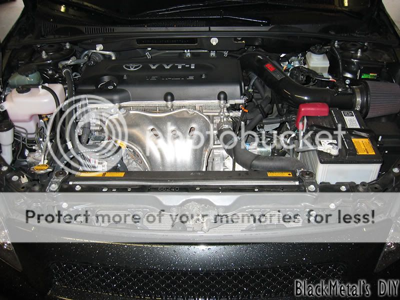
Stock Motor (minus SRI) not much to say other than it’s a reference
These first two steps are not necessary, but it’s nice to give your engine a little physical before taking it to surgery. I would recommend doing a Compression Check on your engine just to make sure you have no internal problems before doing a power mod – you’ll just make the problem worse!
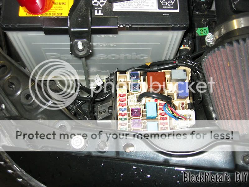
Step 1 – Open your fuse cover under your hood and pull out the EFI fuse, it’s a 20A yellow fuse this will stop your fuel system from injecting any fuel while doing the Compression Check… I’m not going to get into much detail how to do this – search here on SL and you’ll find a thread how to do a Compression check.
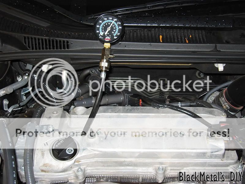
Step 2 – Rent a Compression Check tool from AutoZone if you don’t have one (it’s “free”) remove all your spark plugs and insert the tool into one of your chambers. Mine read the following (from Left to Right) 180, 175, 177, 181 all units are in PSI.
Install all of your spark plugs and put everything back together (but leave the plastic cover off, makes it easier to work) Start your car just to make sure everything works just to be on the safe side.
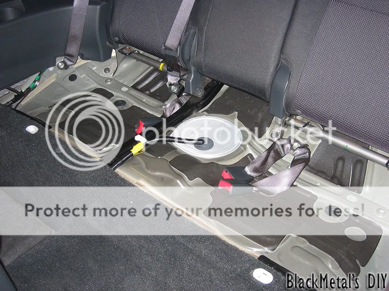
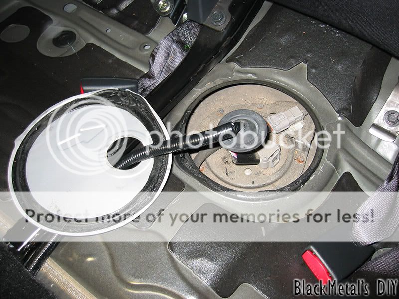
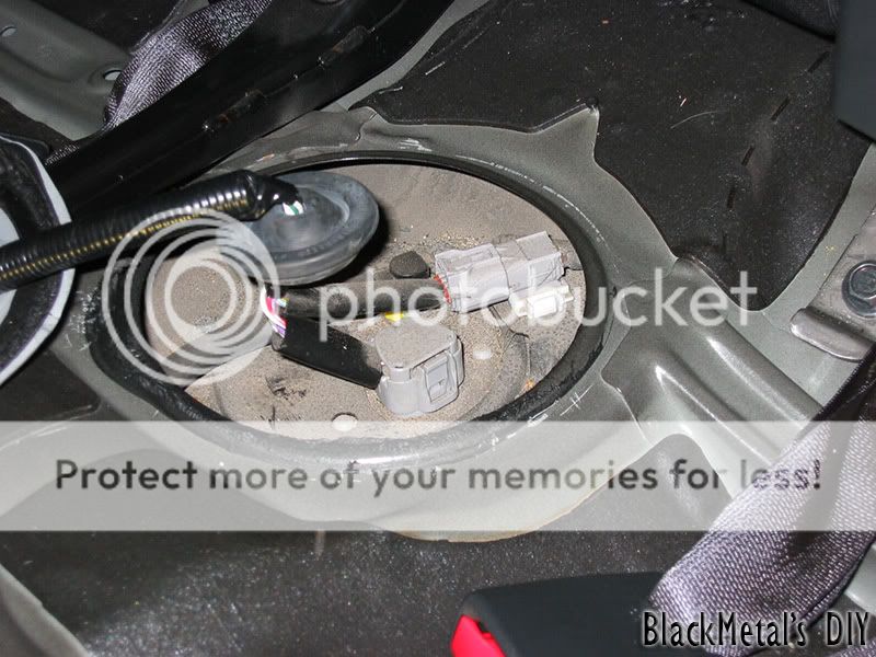
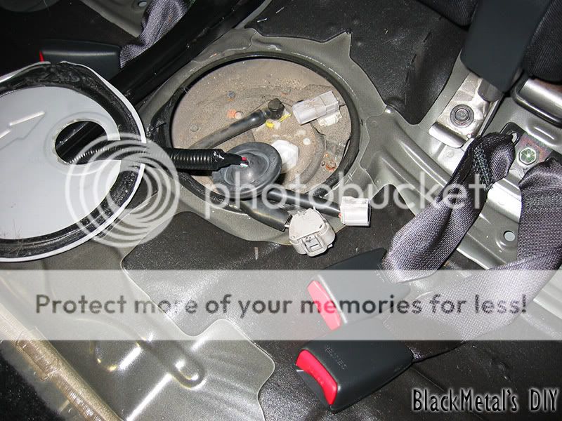
Step 3 – Remove any Air Intake or Stock Intake box. Then remove your back seat because you need to relieve the pressure from your fuel line. To do this get a small flat head screw driver and work your way around the metal cover. Once you pry that off you will see two gray connectors – unplug both of them (the flat one is a P.I.T.A.). Proceed to start your car, it will run for about 3-4 seconds and die out, repeat this a few times to try and get as much fuel out of the line as possible.
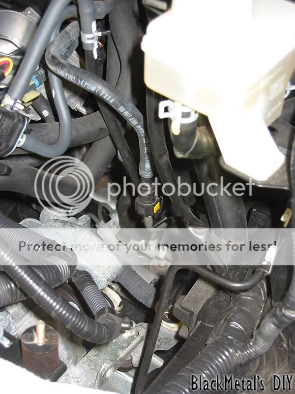
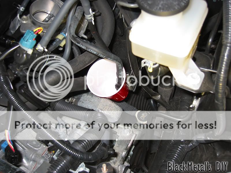
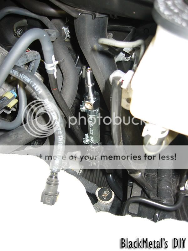
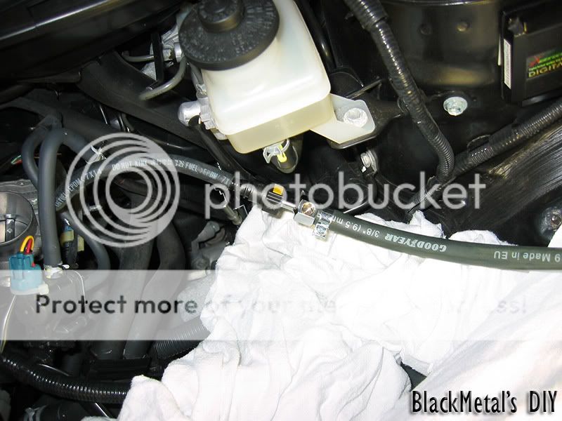
Step 4 – (****NOTE: Disconnect the NEGATIVE battery terminal at this point ****) Once you relieved the fuel line pressure go to the front of your car and look by the Brake Fluid reservoir, you will see a hose labeled “Fuel Line DON’T KINK” – follow that hose all the way down till you see a connector encased in a plastic holder. Gently remove the retaining holder by pushing back on it (it will not come completely off, but enough so you can disconnect the line). One you remove the holder grab a cup and a rag, squeeze the two yellow tabs on each side to disconnect the fuel line (**Gas WILL spill out, so please be very careful and work in a ventilated area – Absolutely NO FLAMES OR SMOKING!**). Let the access fuel drain into the cup, it will take a few seconds, then discard the fuel in the cup somewhere safe, keeping the rag wrapped around the open line.
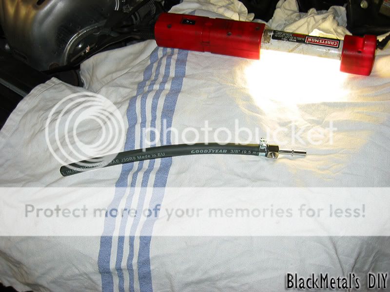
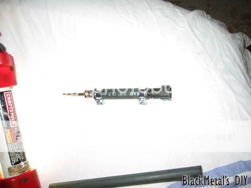
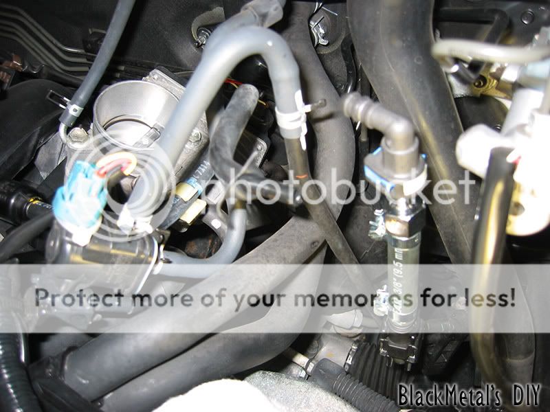
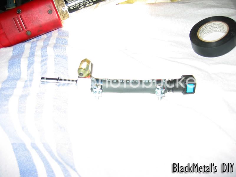
Step 5 – Start to assemble your fuel line “tap” by attaching the metal connector with tap to one end, and the straight plastic connector to the other end, clap down both ends with the provided clamps.
Step 6 – Connect the plastic end of the tap to your main fuel feed line with the plastic holder.
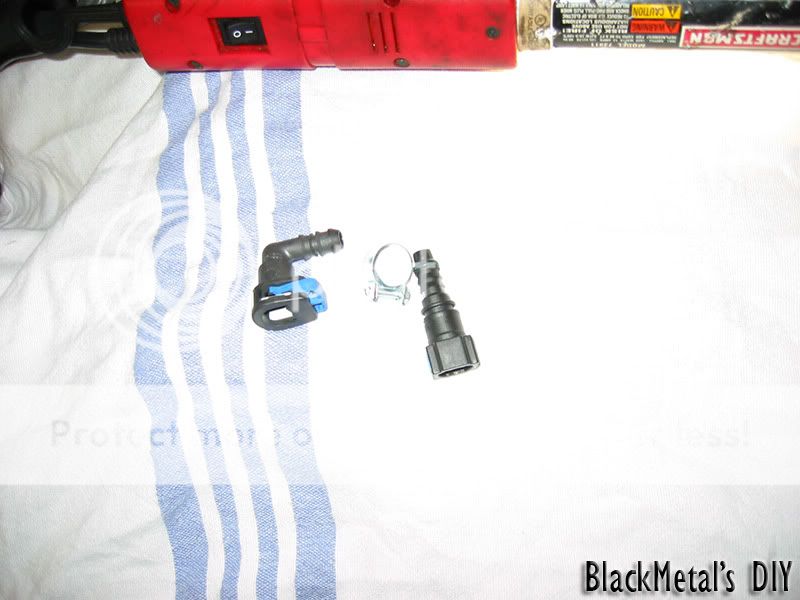
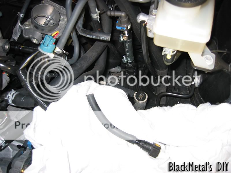
*Optional step – do at your OWN RISK!* - I wasn’t happy with how much extra factory fuel line there was, so I shortened it. To do this you MUST NOTE that the rubber shield on the factory fuel line is only a sheath, under that rubber jacket is the actual hard plastic fuel line. I cut the factory fuel line to size and peeled the rubber jacket back to expose the actual fuel line and created another small piece from the supplied fuel line in the kit. I used the second connector provided in the kit which is a right angle connector and made a splice. The factory fuel line is small enough that the fuel line in the kit slips right over the expose hard plastic line. I clamped down both ends very well.
Step 7 – If you choose to leave the factory fuel line alone, just go ahead and connect the fuel line right back on to the tap.
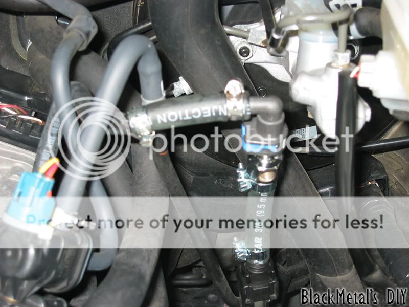
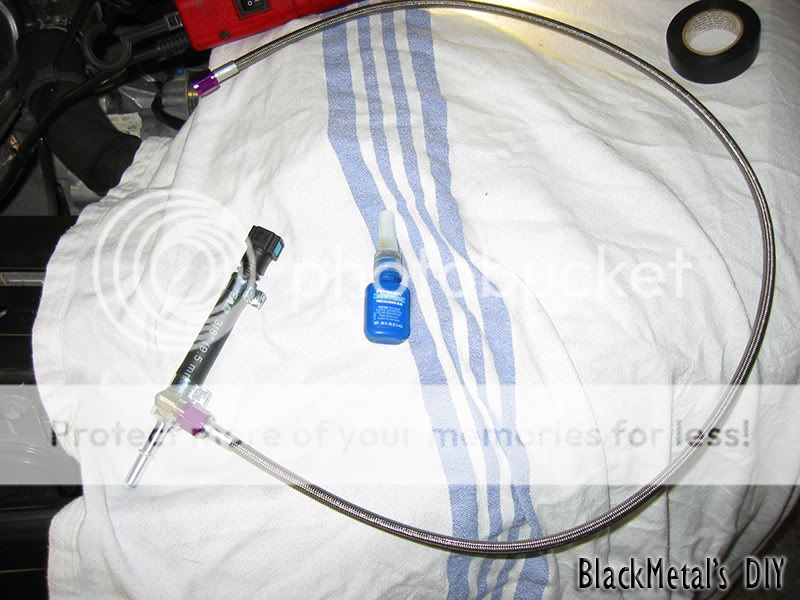
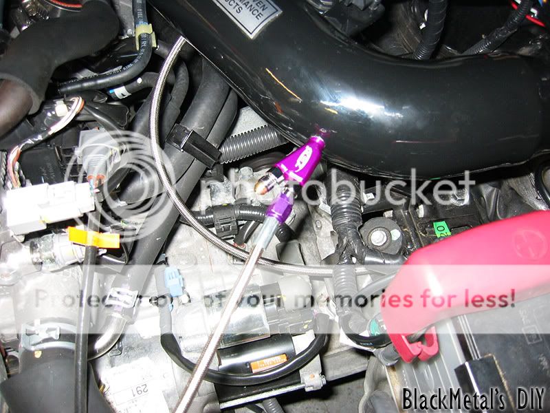
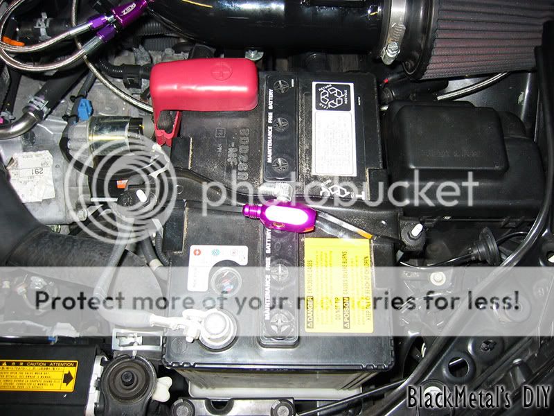
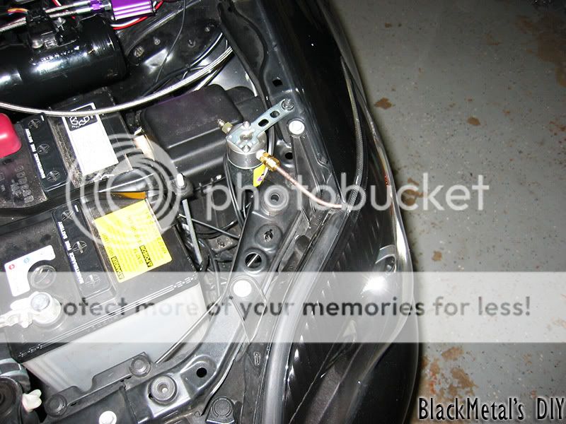
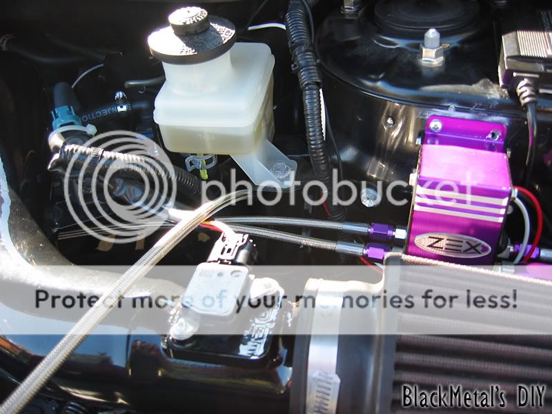
Step 8 – Now grab your bottle of Thread Lock, dab some on the fitting that goes into the hole on the metal tap connector, wrench it down a bit – not TOO hard or you’ll strip the threads. Then take the 3ft. supplied steel braided hose and put a dab of Thread Lock on that end also, wrench that down too – remember, not TOO hard.
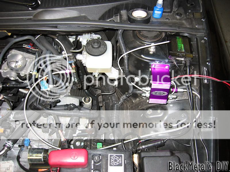
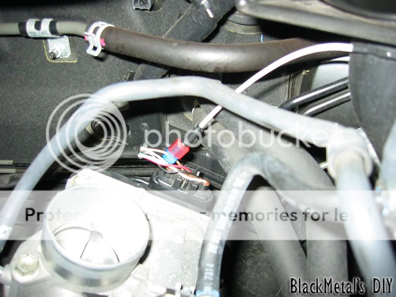
Step 9 – Find a location to mount the controller, I found a great spot on the suspension tower and it won’t interfere with an INJEN SRI filter for ‘07/’08/’09 models. USE A GOOD DRILL BIT, I broke two in the process and one of the supplied “self-tapping” screws (notice one screw missing in the pic on the right hole of the controller). After you mount the controller, install your fuel tap on the car with the braided steel line and route the line in a manner that it won’t interfere with anything. Zip tie it if you want to, just make sure you leave some slack (I didn’t need to tie it down). Put some thread lock on the “FUEL IN” side of the controller and attach the fuel line, wrench it down gently (All these threads are EASY to strip).
Step 10 – Your controller will have three wires, White, Red, and Black. The white wire is the one we are interested in for now. This wire is your TPS (Throttle Position Sensor) wire. The kit came with a supplied resistor in heat-shrink tubing (with white wires on both ends) – you must use this resistor so you don’t throw a code temporally while the system is armed and you’re at WOT. This resistor will not impact the performance of your nitrous kit; it only isolates it from creating interference. Also, you are supplied with a wire splice with a female spade connector on the back of it – Your main throttle body assembly has a wire harness on it with many different wires, you are interested in the BROWN wire on this harness. This is your TPS wire you need to splice into for the controller to detect when you’re at WOT. Assemble the wire splice with the resistor crimped into one end, then use a barrel connector to connect the resistor wire and the controller TPS wire together (recommend wrapping the connectors in Black Electrical Tape). Route this wire to avoid any interference with anything (**NOTE: Leave slack on this TPS wire for Engine Torque movements**)
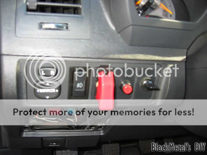
Step 11 – Now it’s time for EVERYONE’s favorite part – running wires through the firewall (you knew this was coming). I’ll make it short and sweet – look right at the top of your firewall on the driver’s side, see the main pass through hole with a billion wires? Make a small incision on the rubber grommet and make sure it goes all the way through to the inside of the car (*BECAREFUL not to cut any wires by accident*). When you’re done making the incision proceed to run the supplied RED wire through the cut in the rubber grommet you just made. Now open your Fuse/Relay access panel on the driver’s side - on the lower half of the dashboard. Put your hand behind the “Blank-Switch-Covers” and pop one out. Get your “Fighter-Jet” cover and the supplied toggle switch and assemble it. Use a 1/2 inch drill bit to drill a hole in the cover you just popped out of the dashboard and assemble it. You will need to tap into a +12v source, I had a pre-existing “Add-a-Circuit” for my hardwired Radar Detector. You can buy one of these from AutoZone for like $5, If you look at the fuse block under the dash by the hood popper you will see two 7.5 amp fuses and a blank spot in between these two 7.5 amp fuses, Install the add-a-circuit in that blank spot because it is switched with the Ignition, install 15 amp fuses on the add-a-circuit. Now get a barrel connector and join the add-a-circuit and one end of the switch together (wrap the barrel connector in electrical tape). Then connect the other end of the switch to the RED wire you just ran into the car from the engine bay and join them together.(* Route these wires in a manner that they will not interfere with the Steering Colum, or any pedals*). Then make the connection under the hood to the Main controller units RED wire. The only wire left on the controller is the BLACK wire which is GROUND. Connect the ground to a GOOD ground post (I can’t stress this enough) sand the area if necessary. Now all your power and sensor wire are connected.
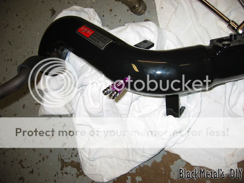
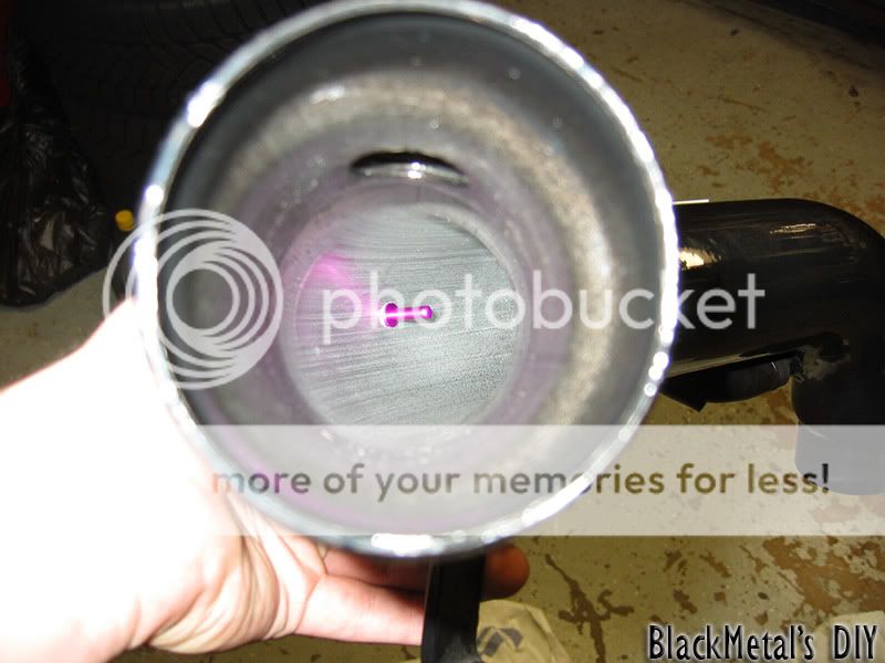
Step 12 – Sweet, now you’re making some progress! This step mainly focuses on an aftermarket intake system, but I’ll briefly explain how to install on a factory air box as well. Get your intake and a tape measure; I’ll be using an INJEN intake. Measure out between 6” - 18” away from the throttle body connection (the more space you give the nitrous/fuel/oxygen to mix - the better). (***Whatever you do make sure you stay BEHIND / AFTER the MAF sensor***). For metal Intake piping ZEX includes a 1/8” NPT tap for your convenience. Drill out an 11/32 hole in your metal intake pipe (refer to my picture on an idea where to drill). Once you drill out the hole use the included tap to make threads in the intake pipe. Clean out any shaving from the intake, scraps won’t be beneficial to your engine performance. Then take the spray nozzle and put some thread lock on the threads. Insert the spray nozzle into your intake pipe and slowly screw it in, when it starts to get hard to turn look inside the intake to make sure the spray nozzle is facing the throttle body and not the intake filter side (this would be a waste of nitrous). Now for those of you that have a stock intake – take the rubber hose and drill a 9/16 inch hole in the hose, you have a special grommet included with the kit that has threads on the inside, install this grommet in the hole you just made and install the spray nozzle like mentioned above.
Step 13 – Take a break, you deserve it!
Step 14 – Proceed to install the intake back into your car, but don’t put the filter on just yet. Think of a suitable way to run two Steel braided lines to the spray nozzle and take into consideration the engine torque – so leave some slack on the lines. Select the jets you want to use, there is a table in the back of the manual that gives you the correct combinations for a 55, 65 and 75 shot. Get your thread lock and dab some on both threads of the spray nozzle and gently wrench them down. Route the line to your controller box and connect them to the appropriate outputs (FUEL OUT / NITROUS OUT) and match it up on the spray nozzle (*This is very important not to mess up*) dab some thread lock on the outputs and gently wrench them down.
Disregard the filter installed in this picture, I was test fitting everything, and your filter should not be installed yet.
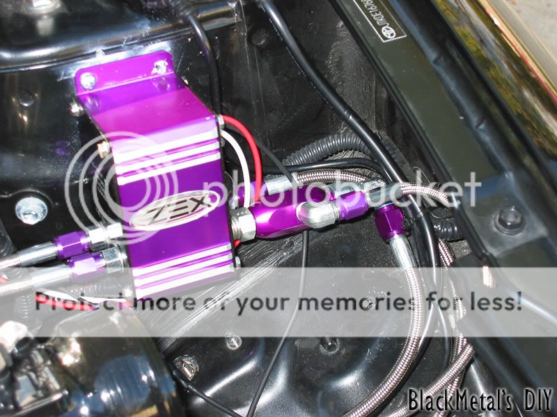
Step 15 – This step is for people that purchased a Purge Kit with their nitrous systems, If you did not purchase a purge kit just skip this step (although I really recommend a purge kit). In the purge kit box you will see an anodized purple tap connector (-4AN) and a right angle tap (-3AN), remove this tap (-3AN) and put some thread lock on it, then reinstall it. Then take the whole assembly and install it on the main controllers NITROUS IN, with a dab of thread lock on the controller – wrench down gently.
Step 16 – Here you are going to have to use some creativity, I can only suggest where to install the purge pipe and the solenoid. I mounted mine by the driver side head light, but I will be relocating it due to the fact it’s freezing my headlight and paint on my fender and hood (not good). Most common place is on the plastic panel where the windshield wipers are (look for pictures / videos on Google for what I’m talking about). The orange “tread-junk” on the fittings for the solenoid are CRAP, use some actual thread lock and dab some on the threads and install both fittings on the IN/OUT sides. After you found a location to mount your purge kit, bend the 12” brass pipe to the location of your choice, cut off any excess pipe. Use the supplied compression fitting for the brass pipe and install with a dab of thread lock to the OUT side of the solenoid. Next get the supplied Steel Braided line and install one end to the IN side of the solenoid, and the other end to the right angle fitting (-3AN) on the purple tap (-4AN) – on the main controllers NITROUS IN.
Step 17 – Now to wire this bad puppy up! (*NOTE – I will only do the write-up for just the purge kit, the Rapid-Fire kit I have is VERY simple to install and shouldn’t require a write-up). In the kit you were supplied with yet another red button for you to push (buttons are good, right?). This is a momentary button and will only make contact for as long as you hold it down. To install the switch pop out another “Black-Switch-Cover” from the dash and drill out a hole using a 25/64 drill bit. Route a +12v wire from one end of the solenoid (*NOTE – the solenoid does not care for polarity, you can use either black wire on the solenoid*) through that same hole you made in the firewall grommet and attach it to one end of the switch, attach the other end of that switch to the +12v add-a-circuit you installed for the Nitrous kit itself. Install the other black wire on the solenoid to a GOOD ground post. Make sure no cables or line will interfere with engine torque or chafing on any sharp metal edges.
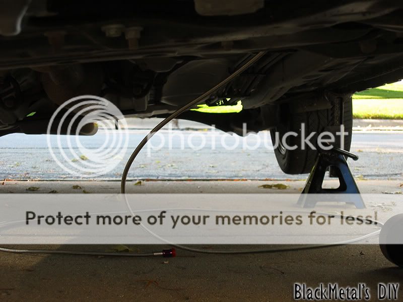
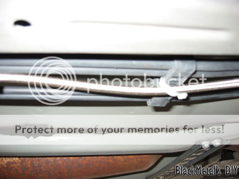
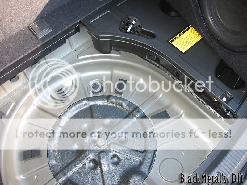
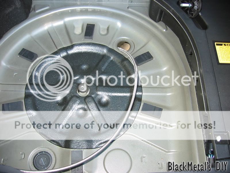
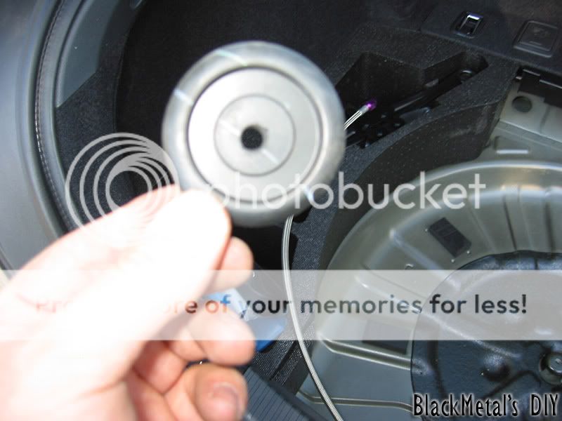
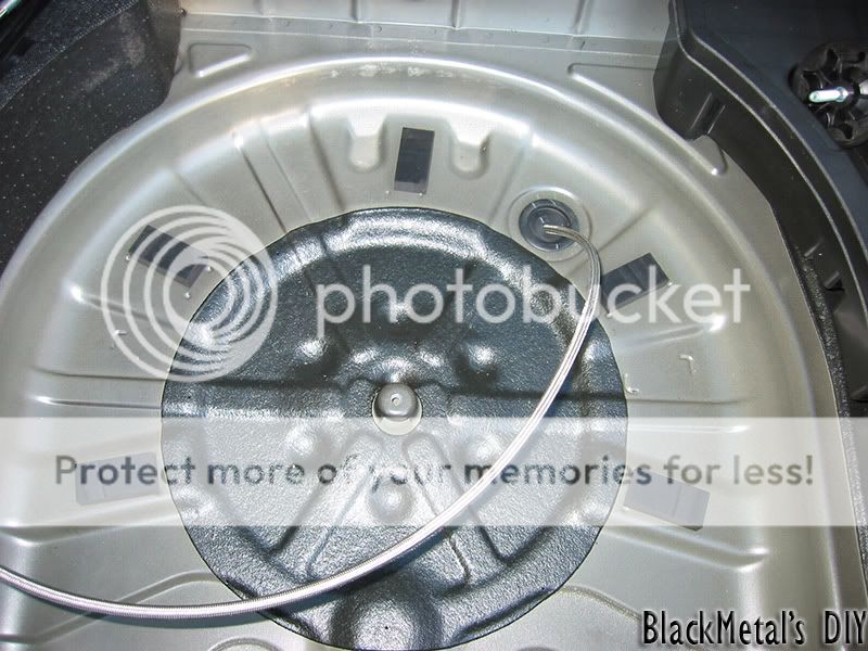
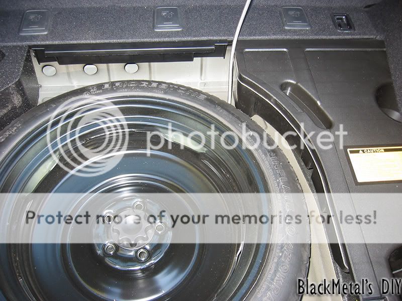
Step 18 – Wow, my fingers hurt lol, two hours of typing straight. Back to business, GOOD NEWS! You are almost ready to start buzzing around in a NITRO-Powered tC, give yourself a pat on the back for getting this far. It’s time to hook up the last line (my opinion this was the easiest part of the install). Unbundle all 16’ of Steel braided cable that came with the Nitrous Kit. Jack up your car anyway that is comfortable for you to get REALLY under it, I mean ALL THE WAY UNDER. (**NOTE – For your safety please use jack stands when using a hydraulic jack, also chock your wheels that are not off the ground and apply the handbrake, poop happens – you don’t want it to be you**). After you car is raised up, look in the engine bay from the top where you made the connections for the fuel tap, see all the metal lines coming from the under side of the car? (should be 4 of them). Route one end of that 16 foot steel braid line down that opening; it is shielded from the control arms movements and anything else that it could interfere with. Pull all of it through until you have enough left in the engine bay to install it to the NITROUS IN on the controller. Take this time to dab a little thread lock on the (-4AN) fitting on the NITROUS IN - and gently wrench it down. Get under your car and straighten out the 16 foot line all the way to the back of the car and let it rest on the ground. You will see 4 lines under the car that run all the way to the back of your car on the driver side, these lines are supported by a bracket that is mounted on the car itself. Notice that there is a blank spot in between the lines, you can’t slip the connector through that opening (that would have been perfect) but you can use behemoth zip ties and follow along those lines all the way to the back of the car. Take all the stuff out of your trunk, look where the spare tire sits, see the rubber plug on the floor (the one that is about 2 O’clock, not the one that is about 8 O’clock). Pull it out and drill a hole through that plug, which is how you will get the Nitrous Steel line inside the trunk. After you finish running the line under the car pull the -4AN connector through the rubber plug you just drilled a hole in, and then install the plug back in the trunk floor. The location of the plug and the Steel line will not interfere with installing the spare tire back in that area.
Step 19 (FINAL STEP) – Installing your 10lbs. bottle. Again, use your creativity for this one, mount it anyway you like as long as the valve side of the bottle sits higher than the bottom of the bottle, and the sticker has to face upwards with the -4AN connector facing down, and the Pressure Safety Disk facing upwards! DO NOT USE THREAD LOCK on this connection, it shouldn’t be necessary, however – If you open the bottle and you hear hissing use some thread lock on it. (***NOTE – Nitrous line are under extremely high pressure, NEVER attempt to work on any nitrous line if it is pressurized, you could get badly injured!***) (***ALSO NOTE – Don’t open the valve on the bottle yet, we still have to “Learn” the voltage curve on the TPS***) At this point attach the negative terminal on the battery and reconnect the fuel line plug under your back seat, put the car’s ignition to the “ON” position, but don’t start it (**CHECK FOR ANY FUEL LEAKS!***). Now Arm the system by flipping the toggle switch on. On the main controller you will see a black button and a bi-colored LED (Red/Green) the LED will be solid red the first time it powers up. Push the black button on the main unit and the LED will turn/stay RED, this indicates that the system is in “Learn mode” wait a few seconds and slowly depresses the gas pedal all the way to WOT. The system will now blink in this pattern – Green/Red/Off – this means that the program is complete. Disarm the system, wait a second, then rearm it (LED should be SOLID green). Press the gas pedal in and you should hear the solenoids click on and off when the TPS wire reads +5v (Don’t worry; gas will not leak into your intake without the nitrous pressure to go with it) and the LED will blink green rapidly. Disarm the system and open the valve on the bottle, check for any nitrous leaks, if there is a leak you will see frost accumulating in that area. Now test your purge! If all is well put everything back together and take it for a spin and enjoy your new NITRO-POWERED Scion tC!
Please leave me some feedback on my DIY Nitrous guide, I spent a LONG time making it and this is my first DIY guide.
Happy Modding!
-BlackMetal
Grab a drink or something because there is going to be some good reading for the next few minutes! So let’s get started shall we?
****Disclaimer – This DIY is intended for people that are comfortable working on cars, if you don’t feel comfortable please DO NOT ATTEMPT THIS INSTALLATION on your own – it’s not so simple of an install, take it to a professional! Also, I am in NO WAY responsible for anything you do to YOUR car, or any injuries you or anyone else encounters in the process. This is intended as a helpful guide, not an installation manual to live by – Most important thing is to HAVE FUN!****
Stock Motor (minus SRI) not much to say other than it’s a reference
These first two steps are not necessary, but it’s nice to give your engine a little physical before taking it to surgery. I would recommend doing a Compression Check on your engine just to make sure you have no internal problems before doing a power mod – you’ll just make the problem worse!
Step 1 – Open your fuse cover under your hood and pull out the EFI fuse, it’s a 20A yellow fuse this will stop your fuel system from injecting any fuel while doing the Compression Check… I’m not going to get into much detail how to do this – search here on SL and you’ll find a thread how to do a Compression check.
Step 2 – Rent a Compression Check tool from AutoZone if you don’t have one (it’s “free”) remove all your spark plugs and insert the tool into one of your chambers. Mine read the following (from Left to Right) 180, 175, 177, 181 all units are in PSI.
Install all of your spark plugs and put everything back together (but leave the plastic cover off, makes it easier to work) Start your car just to make sure everything works just to be on the safe side.
Step 3 – Remove any Air Intake or Stock Intake box. Then remove your back seat because you need to relieve the pressure from your fuel line. To do this get a small flat head screw driver and work your way around the metal cover. Once you pry that off you will see two gray connectors – unplug both of them (the flat one is a P.I.T.A.). Proceed to start your car, it will run for about 3-4 seconds and die out, repeat this a few times to try and get as much fuel out of the line as possible.
Step 4 – (****NOTE: Disconnect the NEGATIVE battery terminal at this point ****) Once you relieved the fuel line pressure go to the front of your car and look by the Brake Fluid reservoir, you will see a hose labeled “Fuel Line DON’T KINK” – follow that hose all the way down till you see a connector encased in a plastic holder. Gently remove the retaining holder by pushing back on it (it will not come completely off, but enough so you can disconnect the line). One you remove the holder grab a cup and a rag, squeeze the two yellow tabs on each side to disconnect the fuel line (**Gas WILL spill out, so please be very careful and work in a ventilated area – Absolutely NO FLAMES OR SMOKING!**). Let the access fuel drain into the cup, it will take a few seconds, then discard the fuel in the cup somewhere safe, keeping the rag wrapped around the open line.
Step 5 – Start to assemble your fuel line “tap” by attaching the metal connector with tap to one end, and the straight plastic connector to the other end, clap down both ends with the provided clamps.
Step 6 – Connect the plastic end of the tap to your main fuel feed line with the plastic holder.
*Optional step – do at your OWN RISK!* - I wasn’t happy with how much extra factory fuel line there was, so I shortened it. To do this you MUST NOTE that the rubber shield on the factory fuel line is only a sheath, under that rubber jacket is the actual hard plastic fuel line. I cut the factory fuel line to size and peeled the rubber jacket back to expose the actual fuel line and created another small piece from the supplied fuel line in the kit. I used the second connector provided in the kit which is a right angle connector and made a splice. The factory fuel line is small enough that the fuel line in the kit slips right over the expose hard plastic line. I clamped down both ends very well.
Step 7 – If you choose to leave the factory fuel line alone, just go ahead and connect the fuel line right back on to the tap.
Step 8 – Now grab your bottle of Thread Lock, dab some on the fitting that goes into the hole on the metal tap connector, wrench it down a bit – not TOO hard or you’ll strip the threads. Then take the 3ft. supplied steel braided hose and put a dab of Thread Lock on that end also, wrench that down too – remember, not TOO hard.
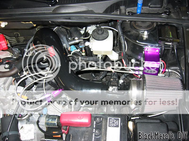
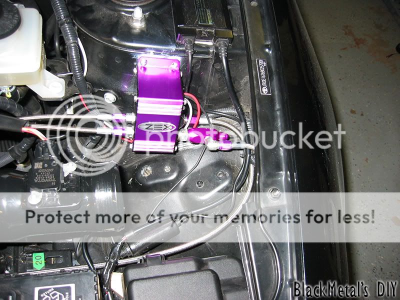
Step 9 – Find a location to mount the controller, I found a great spot on the suspension tower and it won’t interfere with an INJEN SRI filter for ‘07/’08/’09 models. USE A GOOD DRILL BIT, I broke two in the process and one of the supplied “self-tapping” screws (notice one screw missing in the pic on the right hole of the controller). After you mount the controller, install your fuel tap on the car with the braided steel line and route the line in a manner that it won’t interfere with anything. Zip tie it if you want to, just make sure you leave some slack (I didn’t need to tie it down). Put some thread lock on the “FUEL IN” side of the controller and attach the fuel line, wrench it down gently (All these threads are EASY to strip).
Step 10 – Your controller will have three wires, White, Red, and Black. The white wire is the one we are interested in for now. This wire is your TPS (Throttle Position Sensor) wire. The kit came with a supplied resistor in heat-shrink tubing (with white wires on both ends) – you must use this resistor so you don’t throw a code temporally while the system is armed and you’re at WOT. This resistor will not impact the performance of your nitrous kit; it only isolates it from creating interference. Also, you are supplied with a wire splice with a female spade connector on the back of it – Your main throttle body assembly has a wire harness on it with many different wires, you are interested in the BROWN wire on this harness. This is your TPS wire you need to splice into for the controller to detect when you’re at WOT. Assemble the wire splice with the resistor crimped into one end, then use a barrel connector to connect the resistor wire and the controller TPS wire together (recommend wrapping the connectors in Black Electrical Tape). Route this wire to avoid any interference with anything (**NOTE: Leave slack on this TPS wire for Engine Torque movements**)
Step 11 – Now it’s time for EVERYONE’s favorite part – running wires through the firewall (you knew this was coming). I’ll make it short and sweet – look right at the top of your firewall on the driver’s side, see the main pass through hole with a billion wires? Make a small incision on the rubber grommet and make sure it goes all the way through to the inside of the car (*BECAREFUL not to cut any wires by accident*). When you’re done making the incision proceed to run the supplied RED wire through the cut in the rubber grommet you just made. Now open your Fuse/Relay access panel on the driver’s side - on the lower half of the dashboard. Put your hand behind the “Blank-Switch-Covers” and pop one out. Get your “Fighter-Jet” cover and the supplied toggle switch and assemble it. Use a 1/2 inch drill bit to drill a hole in the cover you just popped out of the dashboard and assemble it. You will need to tap into a +12v source, I had a pre-existing “Add-a-Circuit” for my hardwired Radar Detector. You can buy one of these from AutoZone for like $5, If you look at the fuse block under the dash by the hood popper you will see two 7.5 amp fuses and a blank spot in between these two 7.5 amp fuses, Install the add-a-circuit in that blank spot because it is switched with the Ignition, install 15 amp fuses on the add-a-circuit. Now get a barrel connector and join the add-a-circuit and one end of the switch together (wrap the barrel connector in electrical tape). Then connect the other end of the switch to the RED wire you just ran into the car from the engine bay and join them together.(* Route these wires in a manner that they will not interfere with the Steering Colum, or any pedals*). Then make the connection under the hood to the Main controller units RED wire. The only wire left on the controller is the BLACK wire which is GROUND. Connect the ground to a GOOD ground post (I can’t stress this enough) sand the area if necessary. Now all your power and sensor wire are connected.
Step 12 – Sweet, now you’re making some progress! This step mainly focuses on an aftermarket intake system, but I’ll briefly explain how to install on a factory air box as well. Get your intake and a tape measure; I’ll be using an INJEN intake. Measure out between 6” - 18” away from the throttle body connection (the more space you give the nitrous/fuel/oxygen to mix - the better). (***Whatever you do make sure you stay BEHIND / AFTER the MAF sensor***). For metal Intake piping ZEX includes a 1/8” NPT tap for your convenience. Drill out an 11/32 hole in your metal intake pipe (refer to my picture on an idea where to drill). Once you drill out the hole use the included tap to make threads in the intake pipe. Clean out any shaving from the intake, scraps won’t be beneficial to your engine performance. Then take the spray nozzle and put some thread lock on the threads. Insert the spray nozzle into your intake pipe and slowly screw it in, when it starts to get hard to turn look inside the intake to make sure the spray nozzle is facing the throttle body and not the intake filter side (this would be a waste of nitrous). Now for those of you that have a stock intake – take the rubber hose and drill a 9/16 inch hole in the hose, you have a special grommet included with the kit that has threads on the inside, install this grommet in the hole you just made and install the spray nozzle like mentioned above.
Step 13 – Take a break, you deserve it!
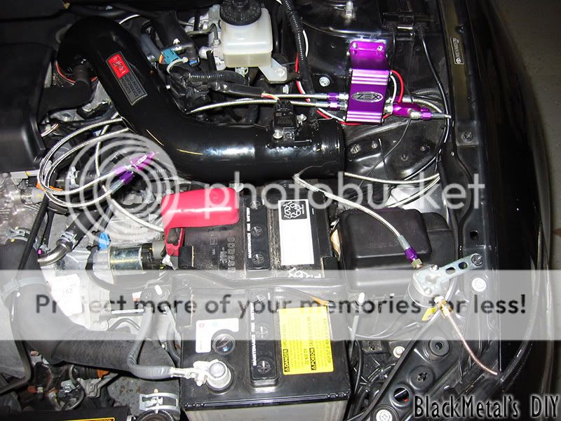
Step 14 – Proceed to install the intake back into your car, but don’t put the filter on just yet. Think of a suitable way to run two Steel braided lines to the spray nozzle and take into consideration the engine torque – so leave some slack on the lines. Select the jets you want to use, there is a table in the back of the manual that gives you the correct combinations for a 55, 65 and 75 shot. Get your thread lock and dab some on both threads of the spray nozzle and gently wrench them down. Route the line to your controller box and connect them to the appropriate outputs (FUEL OUT / NITROUS OUT) and match it up on the spray nozzle (*This is very important not to mess up*) dab some thread lock on the outputs and gently wrench them down.
Disregard the filter installed in this picture, I was test fitting everything, and your filter should not be installed yet.
Step 15 – This step is for people that purchased a Purge Kit with their nitrous systems, If you did not purchase a purge kit just skip this step (although I really recommend a purge kit). In the purge kit box you will see an anodized purple tap connector (-4AN) and a right angle tap (-3AN), remove this tap (-3AN) and put some thread lock on it, then reinstall it. Then take the whole assembly and install it on the main controllers NITROUS IN, with a dab of thread lock on the controller – wrench down gently.
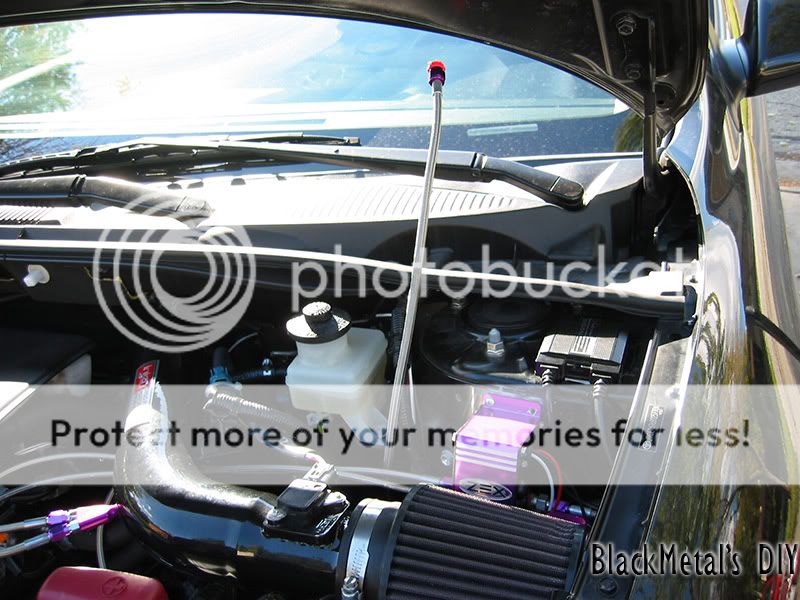
Step 16 – Here you are going to have to use some creativity, I can only suggest where to install the purge pipe and the solenoid. I mounted mine by the driver side head light, but I will be relocating it due to the fact it’s freezing my headlight and paint on my fender and hood (not good). Most common place is on the plastic panel where the windshield wipers are (look for pictures / videos on Google for what I’m talking about). The orange “tread-junk” on the fittings for the solenoid are CRAP, use some actual thread lock and dab some on the threads and install both fittings on the IN/OUT sides. After you found a location to mount your purge kit, bend the 12” brass pipe to the location of your choice, cut off any excess pipe. Use the supplied compression fitting for the brass pipe and install with a dab of thread lock to the OUT side of the solenoid. Next get the supplied Steel Braided line and install one end to the IN side of the solenoid, and the other end to the right angle fitting (-3AN) on the purple tap (-4AN) – on the main controllers NITROUS IN.
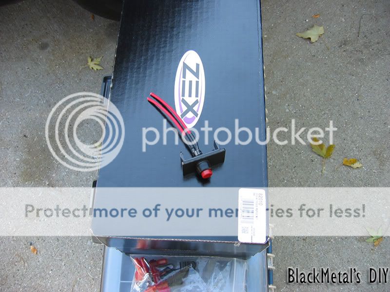
Step 17 – Now to wire this bad puppy up! (*NOTE – I will only do the write-up for just the purge kit, the Rapid-Fire kit I have is VERY simple to install and shouldn’t require a write-up). In the kit you were supplied with yet another red button for you to push (buttons are good, right?). This is a momentary button and will only make contact for as long as you hold it down. To install the switch pop out another “Black-Switch-Cover” from the dash and drill out a hole using a 25/64 drill bit. Route a +12v wire from one end of the solenoid (*NOTE – the solenoid does not care for polarity, you can use either black wire on the solenoid*) through that same hole you made in the firewall grommet and attach it to one end of the switch, attach the other end of that switch to the +12v add-a-circuit you installed for the Nitrous kit itself. Install the other black wire on the solenoid to a GOOD ground post. Make sure no cables or line will interfere with engine torque or chafing on any sharp metal edges.
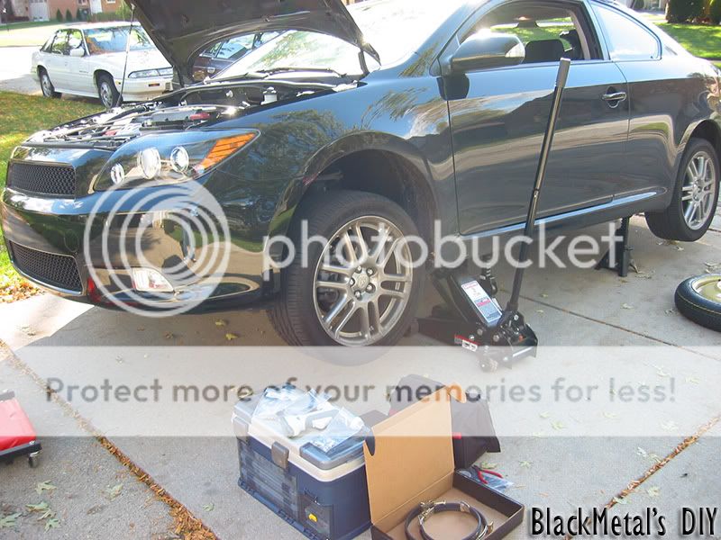
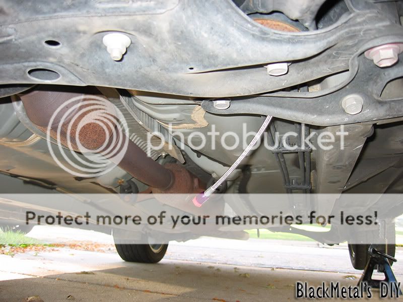
Step 18 – Wow, my fingers hurt lol, two hours of typing straight. Back to business, GOOD NEWS! You are almost ready to start buzzing around in a NITRO-Powered tC, give yourself a pat on the back for getting this far. It’s time to hook up the last line (my opinion this was the easiest part of the install). Unbundle all 16’ of Steel braided cable that came with the Nitrous Kit. Jack up your car anyway that is comfortable for you to get REALLY under it, I mean ALL THE WAY UNDER. (**NOTE – For your safety please use jack stands when using a hydraulic jack, also chock your wheels that are not off the ground and apply the handbrake, poop happens – you don’t want it to be you**). After you car is raised up, look in the engine bay from the top where you made the connections for the fuel tap, see all the metal lines coming from the under side of the car? (should be 4 of them). Route one end of that 16 foot steel braid line down that opening; it is shielded from the control arms movements and anything else that it could interfere with. Pull all of it through until you have enough left in the engine bay to install it to the NITROUS IN on the controller. Take this time to dab a little thread lock on the (-4AN) fitting on the NITROUS IN - and gently wrench it down. Get under your car and straighten out the 16 foot line all the way to the back of the car and let it rest on the ground. You will see 4 lines under the car that run all the way to the back of your car on the driver side, these lines are supported by a bracket that is mounted on the car itself. Notice that there is a blank spot in between the lines, you can’t slip the connector through that opening (that would have been perfect) but you can use behemoth zip ties and follow along those lines all the way to the back of the car. Take all the stuff out of your trunk, look where the spare tire sits, see the rubber plug on the floor (the one that is about 2 O’clock, not the one that is about 8 O’clock). Pull it out and drill a hole through that plug, which is how you will get the Nitrous Steel line inside the trunk. After you finish running the line under the car pull the -4AN connector through the rubber plug you just drilled a hole in, and then install the plug back in the trunk floor. The location of the plug and the Steel line will not interfere with installing the spare tire back in that area.
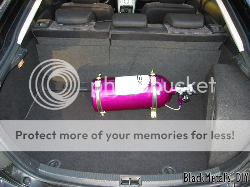
Step 19 (FINAL STEP) – Installing your 10lbs. bottle. Again, use your creativity for this one, mount it anyway you like as long as the valve side of the bottle sits higher than the bottom of the bottle, and the sticker has to face upwards with the -4AN connector facing down, and the Pressure Safety Disk facing upwards! DO NOT USE THREAD LOCK on this connection, it shouldn’t be necessary, however – If you open the bottle and you hear hissing use some thread lock on it. (***NOTE – Nitrous line are under extremely high pressure, NEVER attempt to work on any nitrous line if it is pressurized, you could get badly injured!***) (***ALSO NOTE – Don’t open the valve on the bottle yet, we still have to “Learn” the voltage curve on the TPS***) At this point attach the negative terminal on the battery and reconnect the fuel line plug under your back seat, put the car’s ignition to the “ON” position, but don’t start it (**CHECK FOR ANY FUEL LEAKS!***). Now Arm the system by flipping the toggle switch on. On the main controller you will see a black button and a bi-colored LED (Red/Green) the LED will be solid red the first time it powers up. Push the black button on the main unit and the LED will turn/stay RED, this indicates that the system is in “Learn mode” wait a few seconds and slowly depresses the gas pedal all the way to WOT. The system will now blink in this pattern – Green/Red/Off – this means that the program is complete. Disarm the system, wait a second, then rearm it (LED should be SOLID green). Press the gas pedal in and you should hear the solenoids click on and off when the TPS wire reads +5v (Don’t worry; gas will not leak into your intake without the nitrous pressure to go with it) and the LED will blink green rapidly. Disarm the system and open the valve on the bottle, check for any nitrous leaks, if there is a leak you will see frost accumulating in that area. Now test your purge! If all is well put everything back together and take it for a spin and enjoy your new NITRO-POWERED Scion tC!
Please leave me some feedback on my DIY Nitrous guide, I spent a LONG time making it and this is my first DIY guide.
Happy Modding!
-BlackMetal


 10-17-2008, 04:30 PM
#12
Senior Member
SL Member
Thread Starter
Join Date: Dec 2007
Location: Des Plaines, IL
Posts: 369
Thanks for all the great feedback guys  ... I'm running a 55 shot for now... It's QUICK... But I had a cold bottle
  ... I'm at work now and I got a nice electric heater, some co-workers want to go for a ride when we go out to lunch so I'm warming up the bottle as I type
  ... Should be better than last night (Bottle was only at 650psi out of 950psi when the bottle is warm (around 75-77 degrees)... I'll let you guys know how this run goes (my car is gonna be packed with people though
  )...
)...
10-17-2008, 05:20 PM
#13
Senior Member
Fail, INC
teamNJCT
SL Member

Join Date: Oct 2005
Location: Connecticut
Posts: 2,068
Well kick the people out and let them smell your nitrous exhaust. And tell us how it is after the heater! And have you buddy film your purge and a couple runs also. Congrats and this is probably gonna be stickied.


 10-18-2008, 02:27 AM
#19
Senior Member
SL Member
Thread Starter
Join Date: Dec 2007
Location: Des Plaines, IL
Posts: 369
Ok, sorry for the long delay - I work two jobs on Friday back-to-back, just got home... The lunch time run was awesome, even with 4 people in the car... Everyone was like "woah" lol... Heated bottle definetly makes a difference (wish I got a bottle warmer when I orderd this)... My first tank is almost empty haha... I'm going to go refill it tomorrow... If the mods find this DIY useful I hope they make it a sticky... Videos will come shortly, I have to relocate my purge first and try to use the blue LED that came with it...
