
DIY-AEM F/IC-now with 2-Step launch control


Thread Starter

Joined: Feb 2008
Posts: 11,271
From: Houston, TX
Here is a Vid to prove it...this is just a test to check it out and I need to do a bit more before i post a DIY on it. parts are cheap for it and doesnt require much to do really.
Also in the Vid iv got the bottom part of the stock air box off so it sounds a little beefier if anyone was wondering.
again this is just a test so far.
_____________________________________________________________________
AEM F/IC 2-Step DIY
This is for off-road use only and is done at your own risk!!!
Supplies
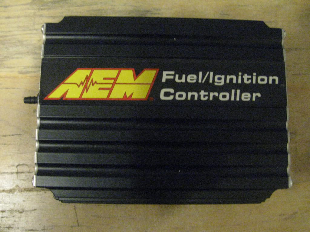
AEM Fic
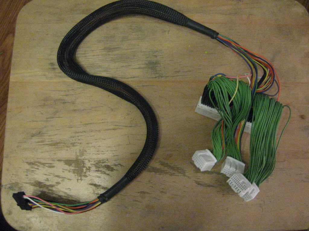
Fic Harness
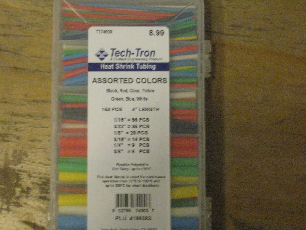
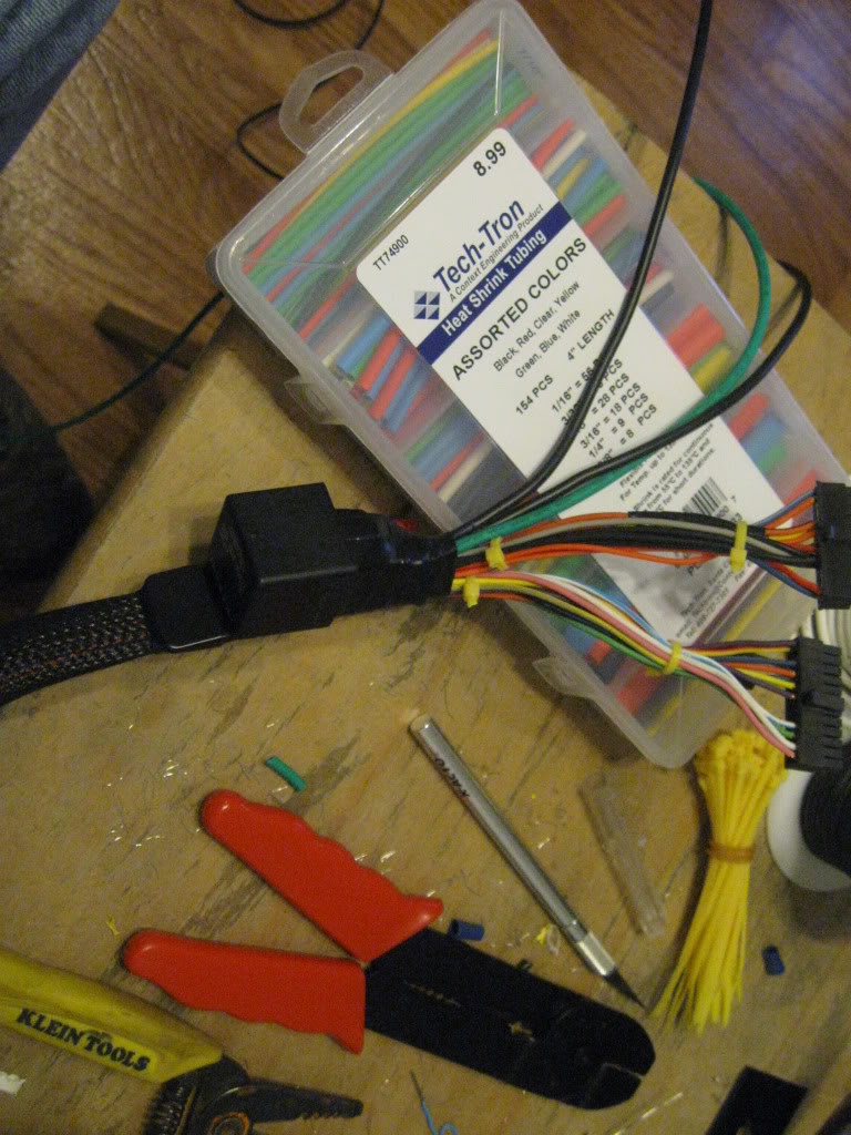
Shrink tube
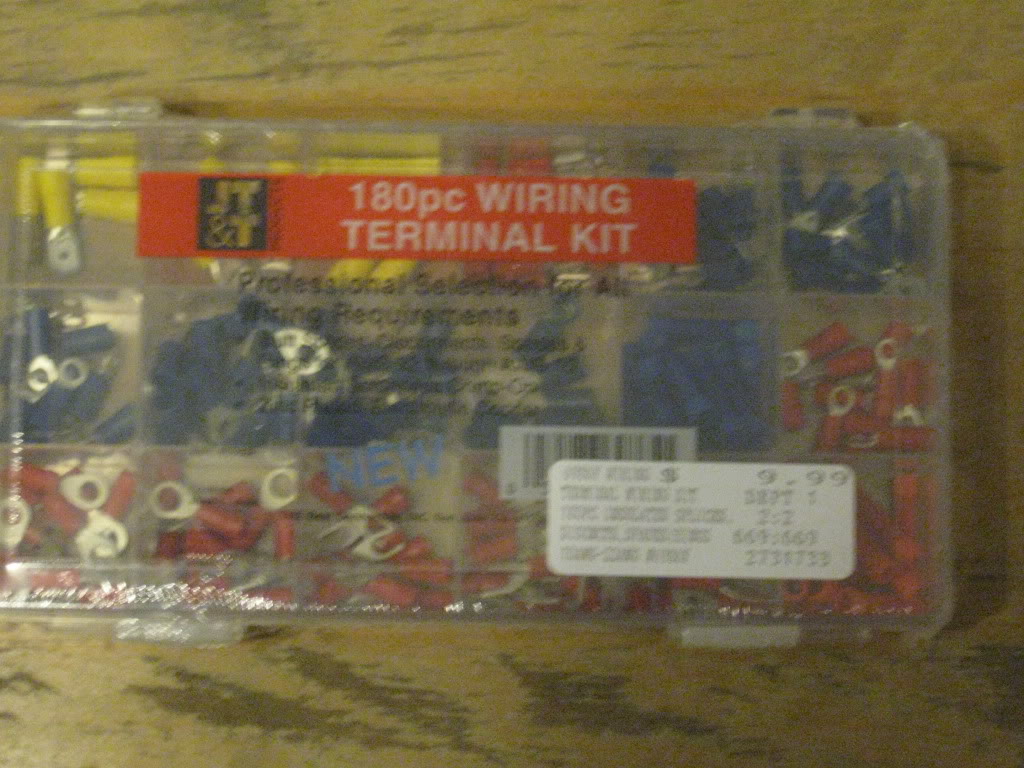
Crimp Connectors
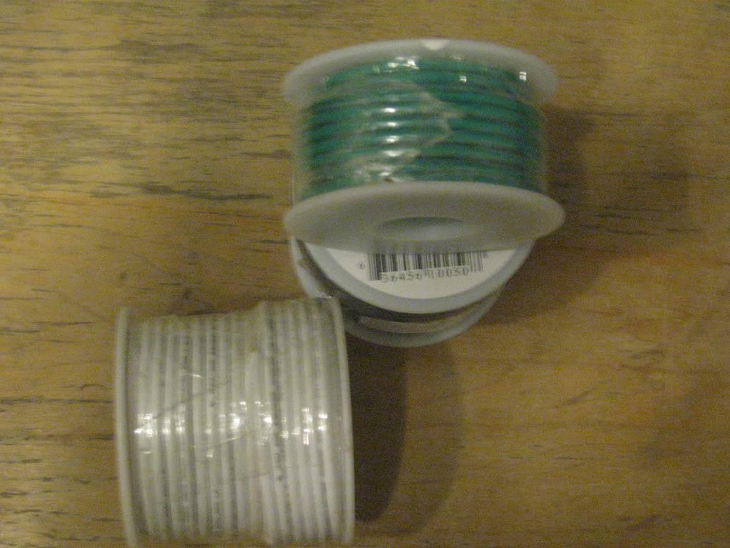
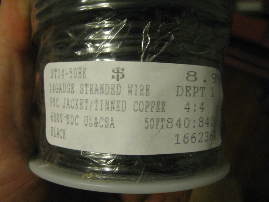
14 Gauge Wire and 24 Gauge Wire
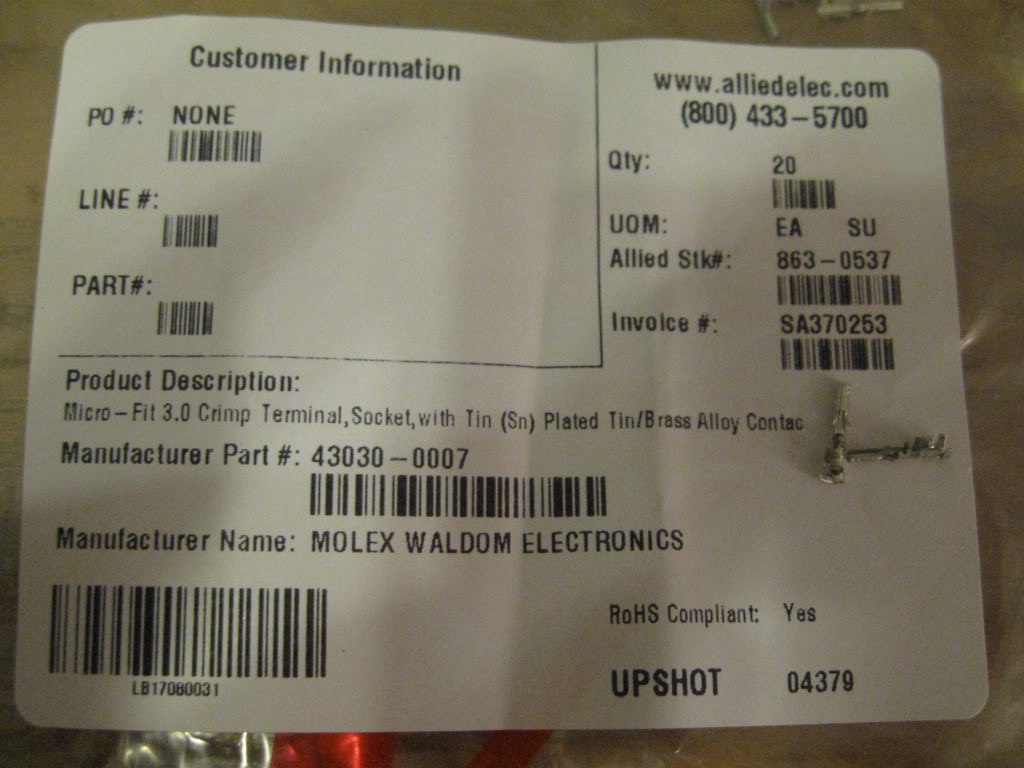
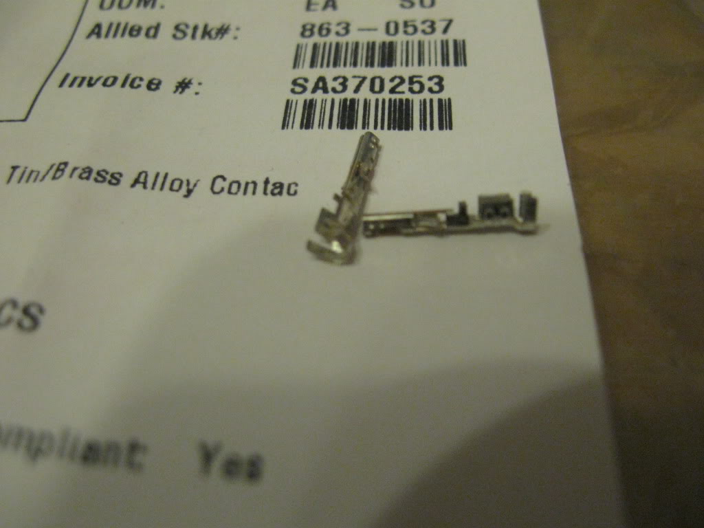
Molex Micro-Fit 3.0 Socket Crimp Terminal (This is if you dont have a spare universal harness to pull pins from and using the boomslang pnp harness. If your hardwired using the universal harness your one lucky guy cause youll save yourself some time)
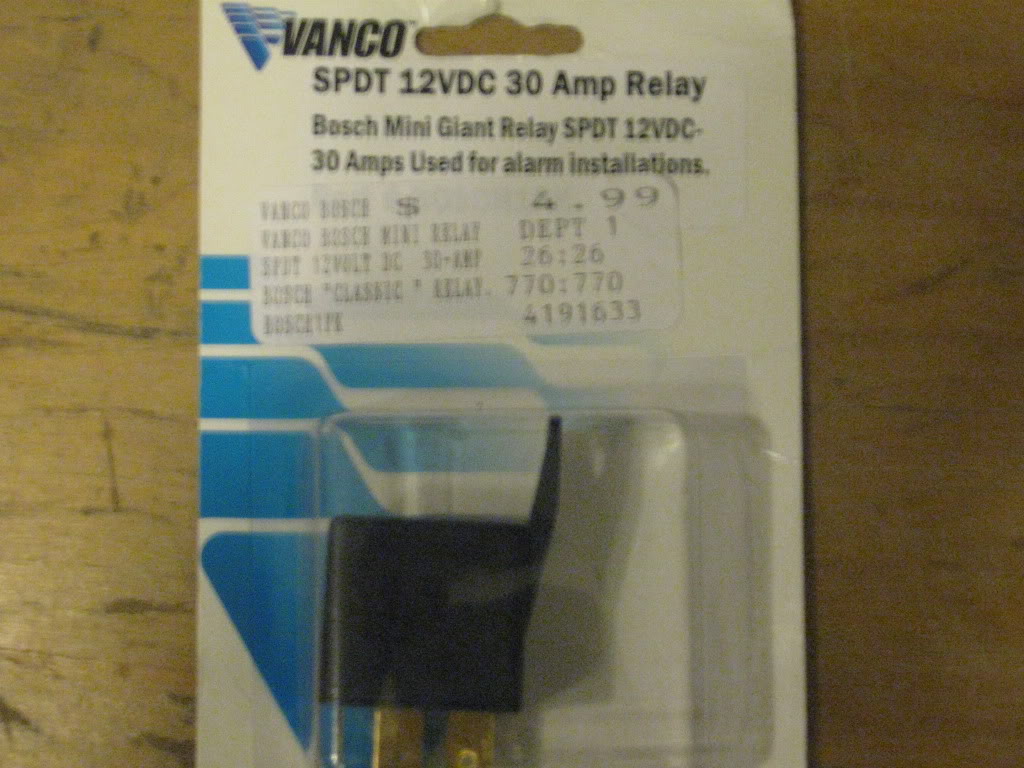
12 Volt 30 Amp Relay (Five pin relay with one "normally closed" contact)
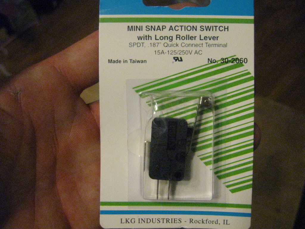
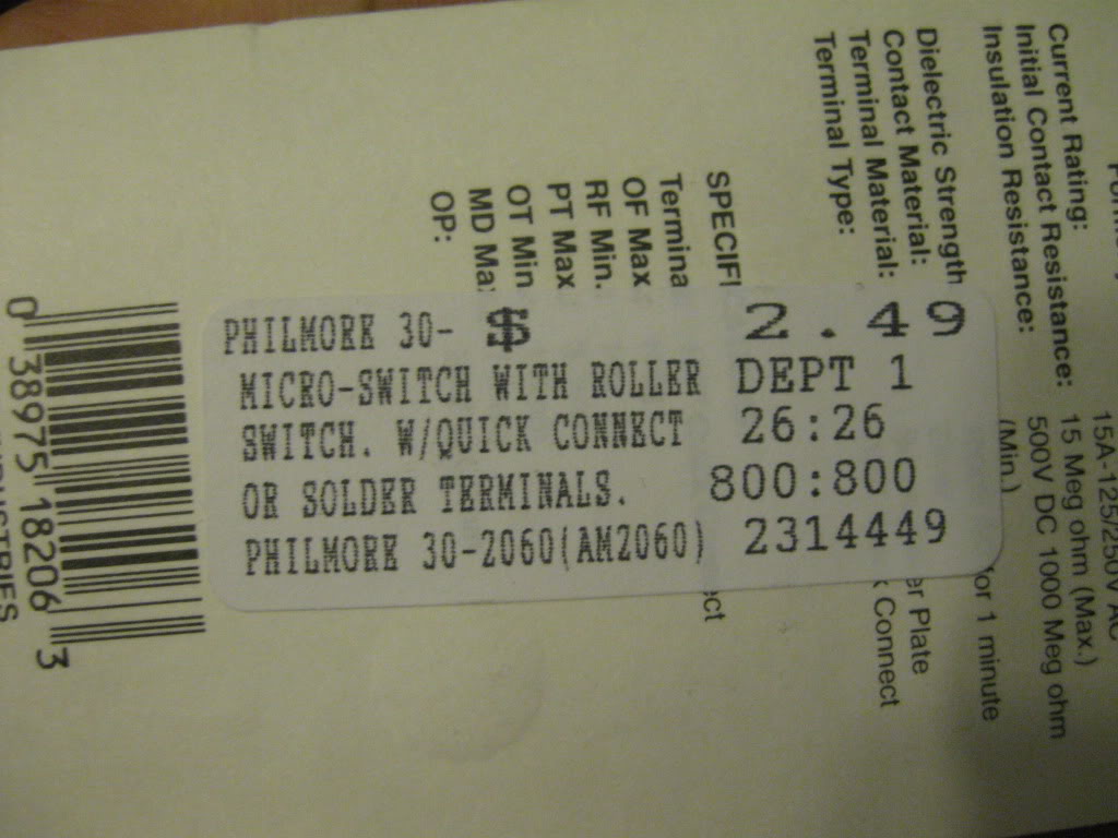
Small Limit Switch (aka Mini snap action switch)
Zip Ties
12 Volt 15 Amp Toggle Switch
Velcro Tape or Double Sided Tape (optional)
Self Taping Sheet Metal Screw (optional)
Red Bull (almost manditory..lol)

Most of this stuff can be found at Fry's electronics except for fic, pnp harness, molex pins. Fic and harness can be found at www.dezod.com and molex pins can be found at www.alliedelec.com .
---------------------------------------------------------------------------
Tools
Crimpers
Stripers
Multi-meter (for checking connections and trouble shooting)
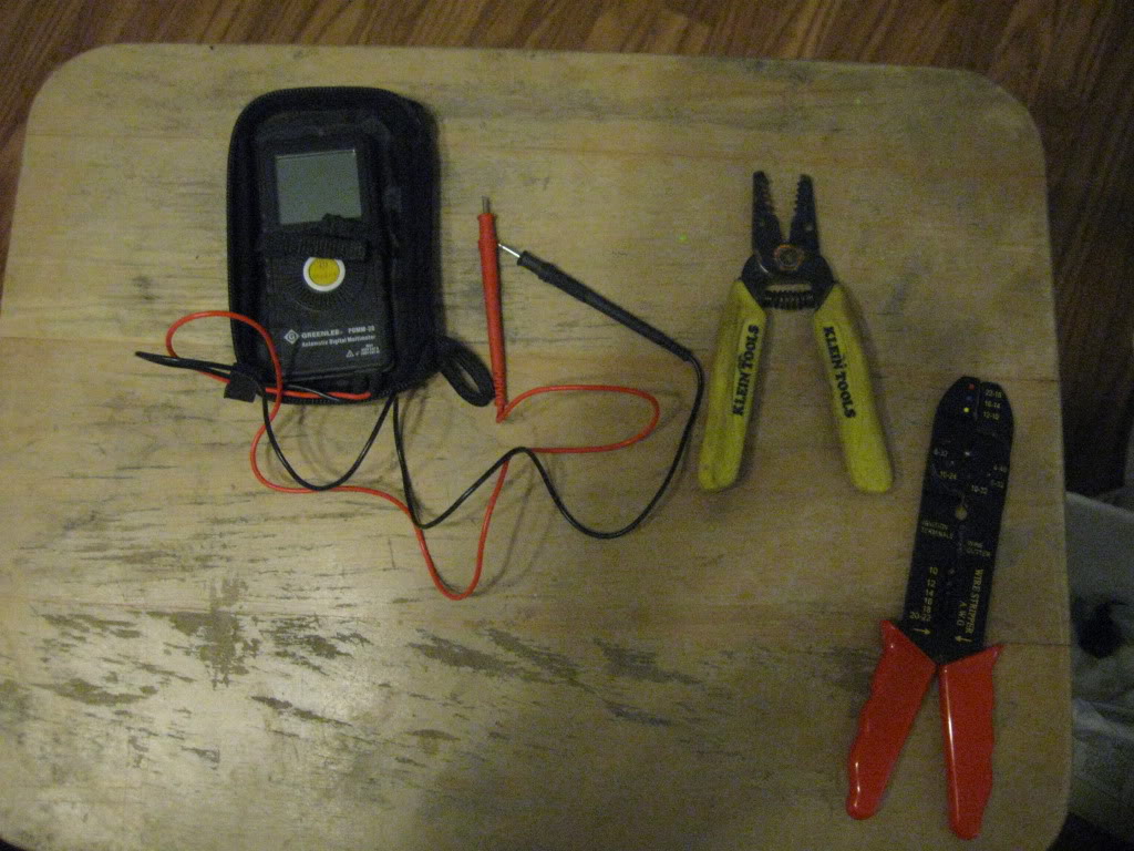
Flat head screw driver
Tiny drill (skill xo, ryobi 4volt driver, etc) (optional)
Philips head screw driver (optional)
Solder
Soldering Iron
Knife
Lighter or heat gun
----------------------------------------------------------------
Pre-wiring
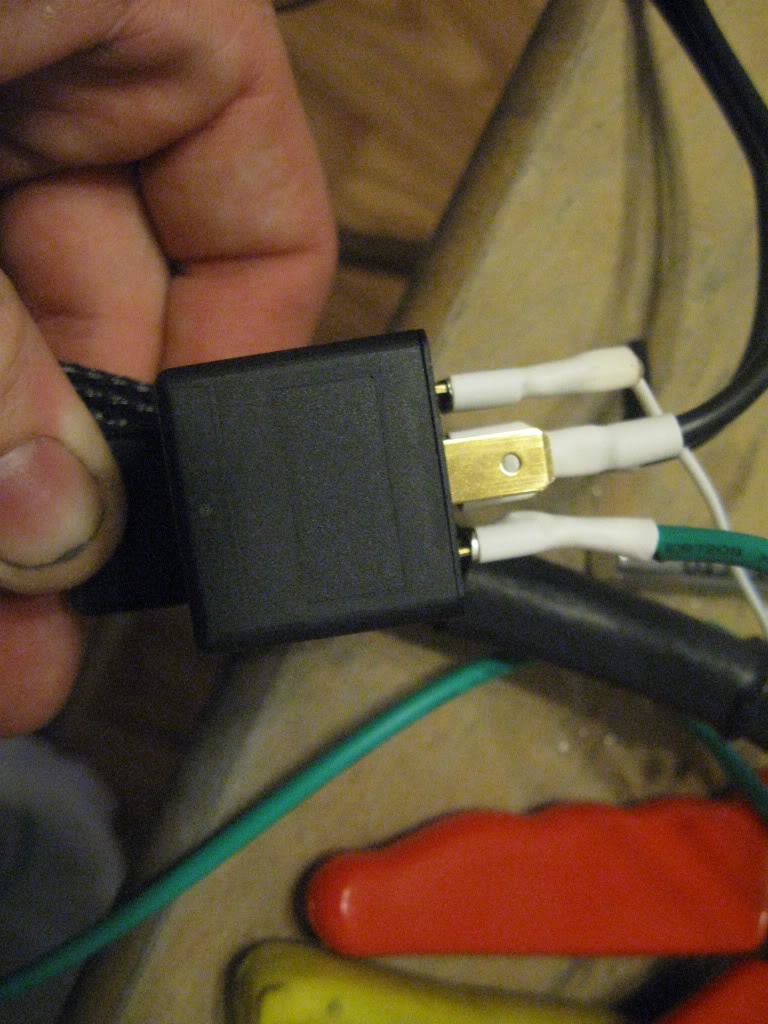
We will start with the relay, take note of the wiring diagram thats on it. Almost all relays have a wiring diagram that will tell you what pins do what.
Break out the relay and find the two pins for the coil. You will need to either pull out a pin from the Fic universal harness or you'll need to grab the 24 gauge wire. Take one end of that wire and crimp on a female spade connector. Heat shrink the wire and connector so nothing can make contact with it from the sides. Plug this wire into one of the pins for the coil on the relay. On my relay this pin is labeled 85.
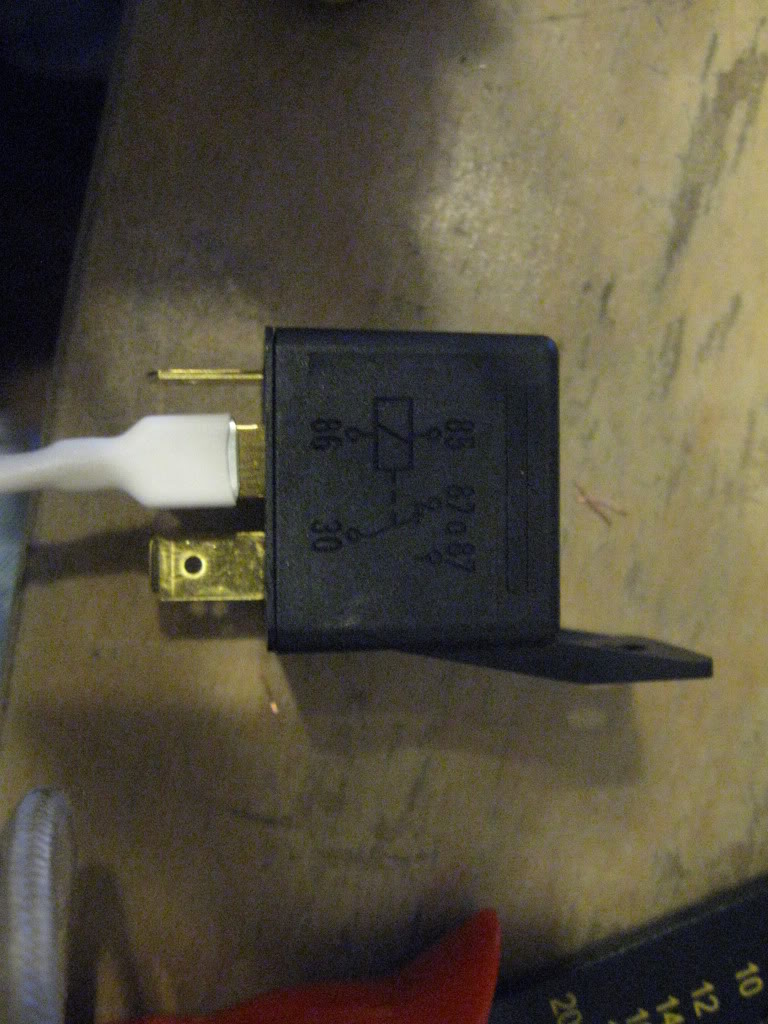
Take the other end of that wire and crimp on a molex micro-fit 3.0 terminal. If using a wire and terminal pulled from the fic universal harness then no need for crimping a molex terminal on.
Now we need to find pin 16 on the 24 pin connector, on my harness pin 16 is on the top row right next to the green wire.
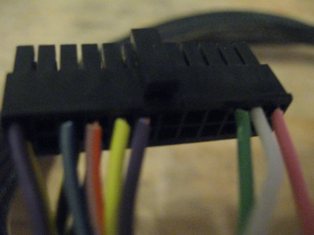
If still unsure of which pin look through your fic wiring instructions thats on your install CD, it will have a complete pin-out for both connectors that plug into the fic.
Now take that wire we were just dealing with and push it into pin 16 of the 24 pin connector.
It should look like this
Make sure you have pushed it in as far as the others, if it doesnt stay firm in the connector or isnt pushed in far enough you will not have proper contact.
Now move to the one pin for the coil of the relay thats left. Its labeled 86 on my relay. This is were we are going to bring a ground to that will come from the limit switch that will be mounted under the clutch pedal so make sure you cut yourself enough wire to do so. It will roughly take about 10ft of wire to be on the safe side.
Unroll some 14 gauge wire for this and crimp on a female spade connector. Heat shrink it to be safe after its been crimped, plug it into the relay.
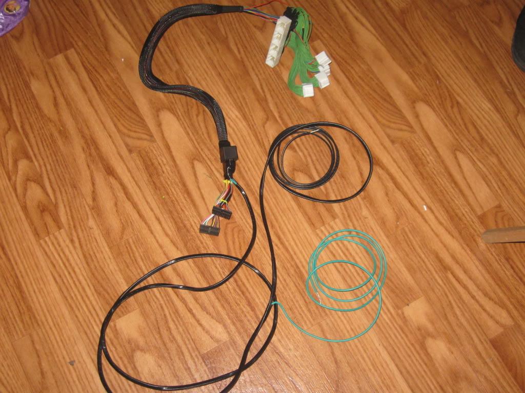
Next we will need two long runs of wire roughly 15ft long each. Thes will go from relay to engine bay.
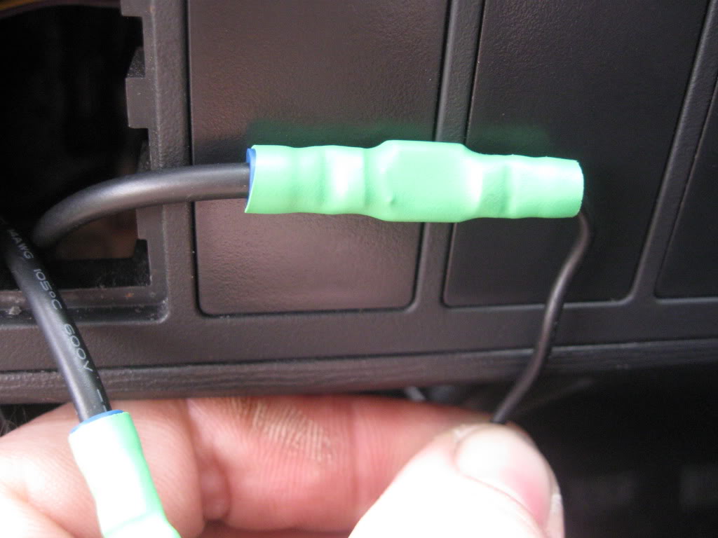
Crimp on one female connector per wire and heat shrink them.
One will be pluged into the common terminal of the relay, on my relay its labeled 30. The other wire needs to be pluged into the relay pin thats a "normally closed" contact. This pin is labeled 87a on my relay.
So far everything should start looking like this
We are almost done with the relay, just need to tape it up to the Fic pnp harness (or mount it someplace in the glove box later)
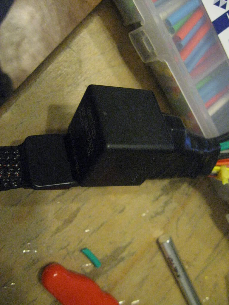
Now we need to splice into the wire thats connected to pin 30 on my relay with another 14 gauge wire thats roughly 5ft long depending on where you tap into. this is one is for the bypass switch (12 volt toggle switch) so you can activate or deactivate the 2 step. Then you will need to take another 5ft long piece of wire and tap into the wire coming from pin 87a on my relay. This too is for the bypass switch. I suggest to make your connections by peeling back a little insulation on the two wires coming from the relay and soldering each bypass wire but a tap (suitcase) connector could be used.
Your just about done with the pre-wire just need to tape up or heat shrink the wires to keep them neat and together.
----------------------------------------------------------------
Wiring
Now that the harness is ready its time to run the wires through the glove box. You can use a coat hanger to fish the wire through to the driverside floor board if it helps. I had the test wires already ther so i used them to pull in the new wires.
Now we are going to drop off the two wires for the bypass switch and the ground at the driver-side floor board, then take the two wires connected to pin 30 & 87a and run them through the fire wall. You can run them through the large grommet located above the pedals. Again I used my test wires to help pull them through the fire wall.
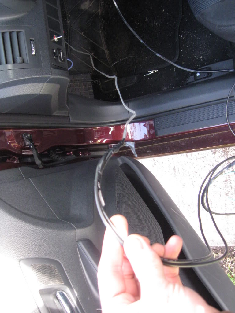
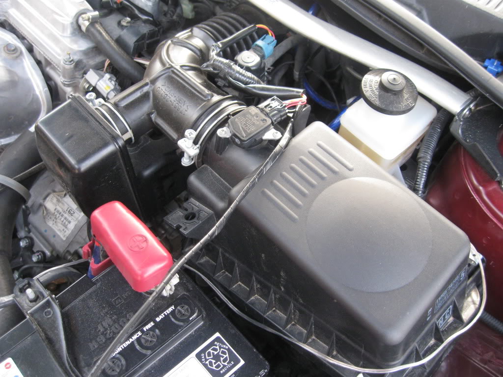
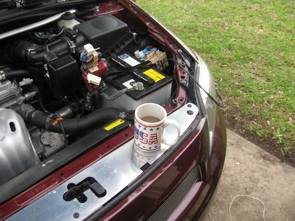
You will need to pull them all the way to the fuse box in the drivers side of the engine bay.
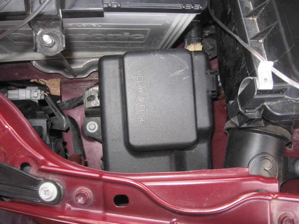
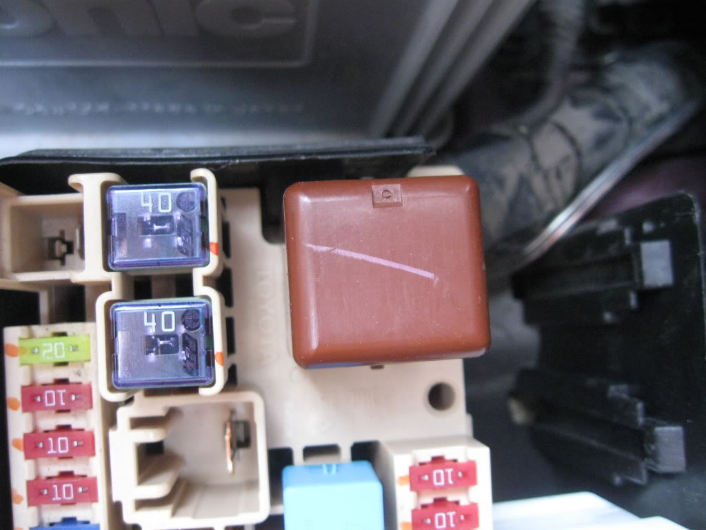
Pop the cover off of the fuse box.
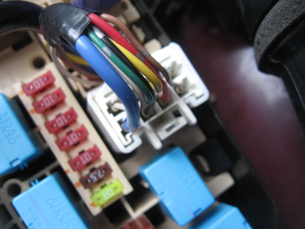
Thes two connectors will need to be disconnected for the moment.
Disconnect battery.
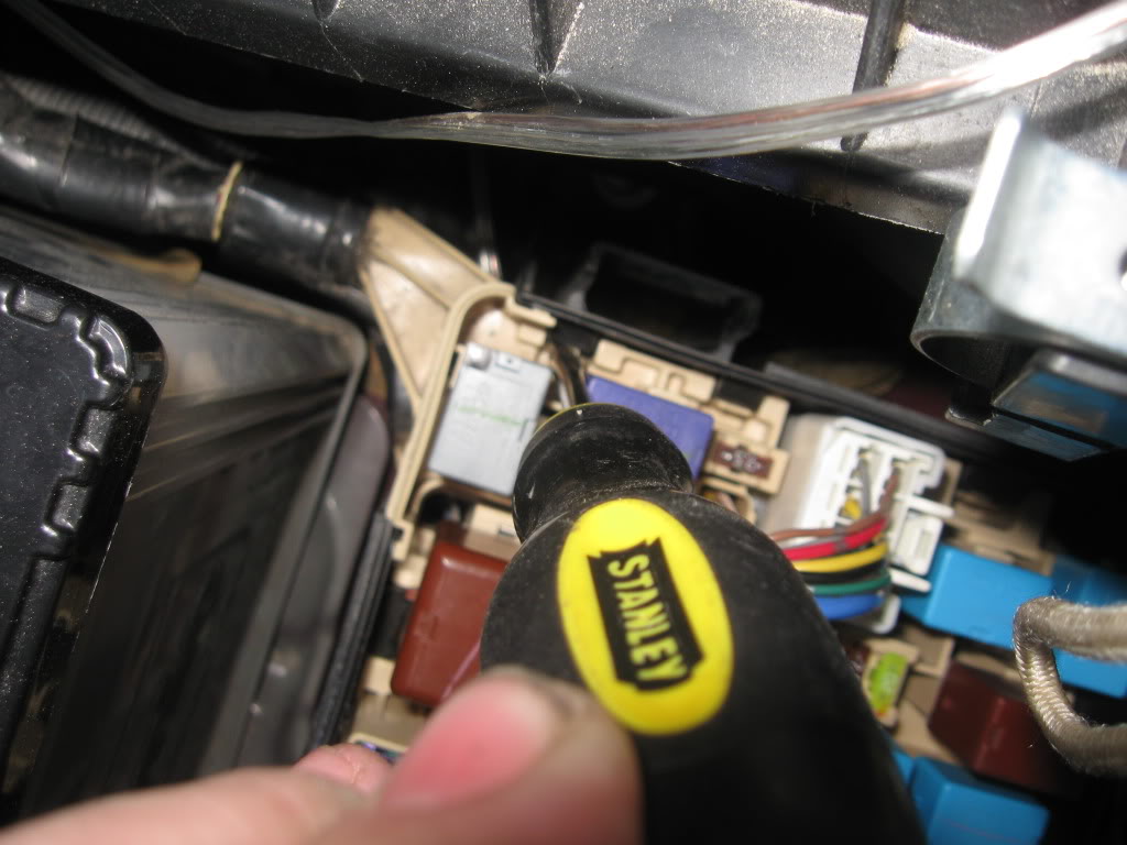
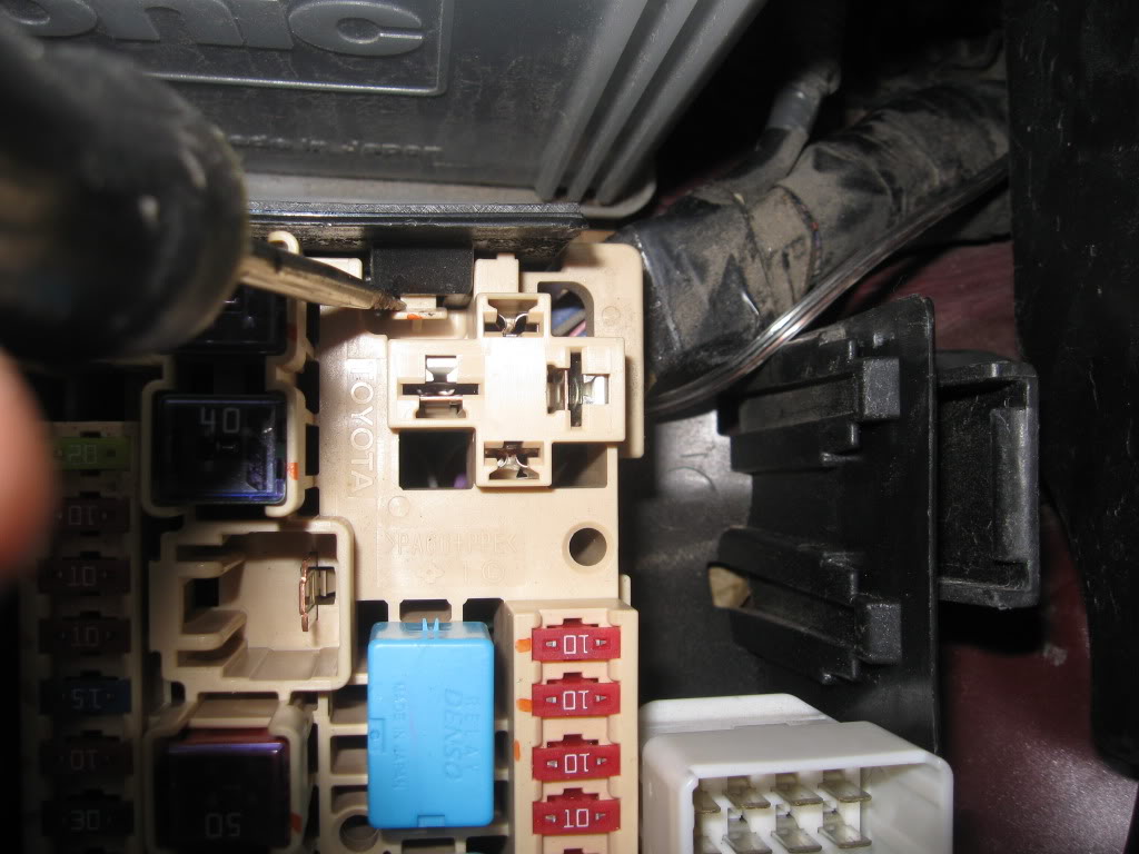
There are two tabs that hold in the small portion of the fuse box that will need to be pulled back to release it. This is where the flat head screw driver comes into play. Hold the tab back with the flat head and gently pull up on the small section. Keep holding it up while you swap over to the other tab and do the same thing.
Pull out the small section of the fuse box and place it out of the way.
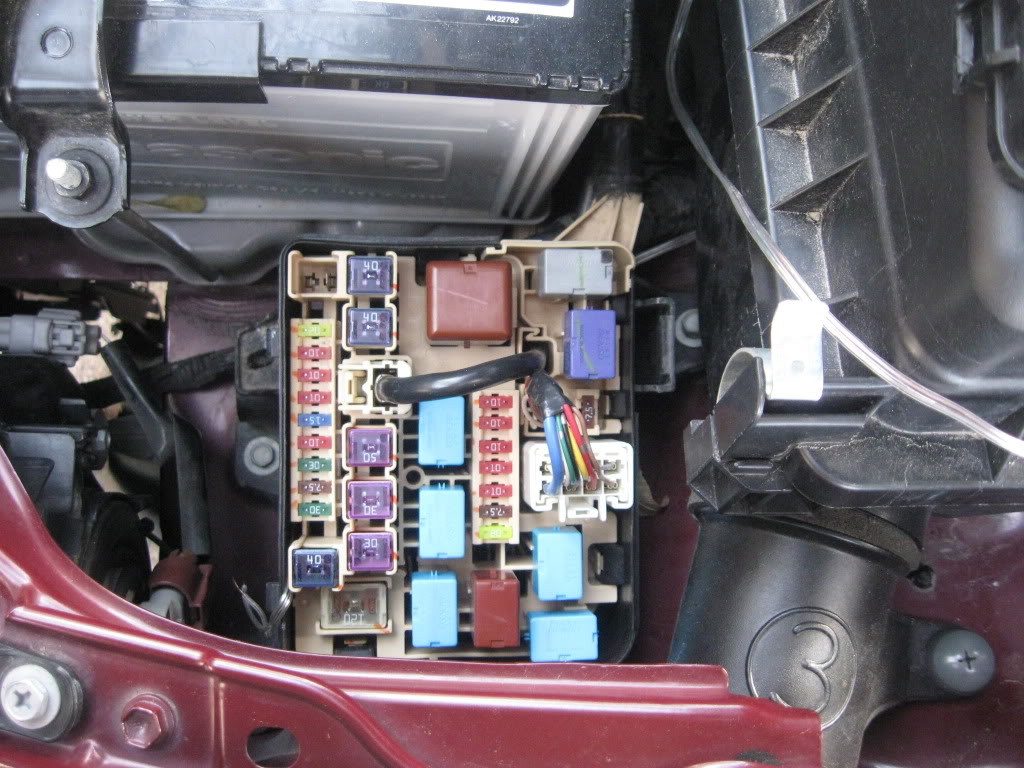
next unplug the brown cube relay.
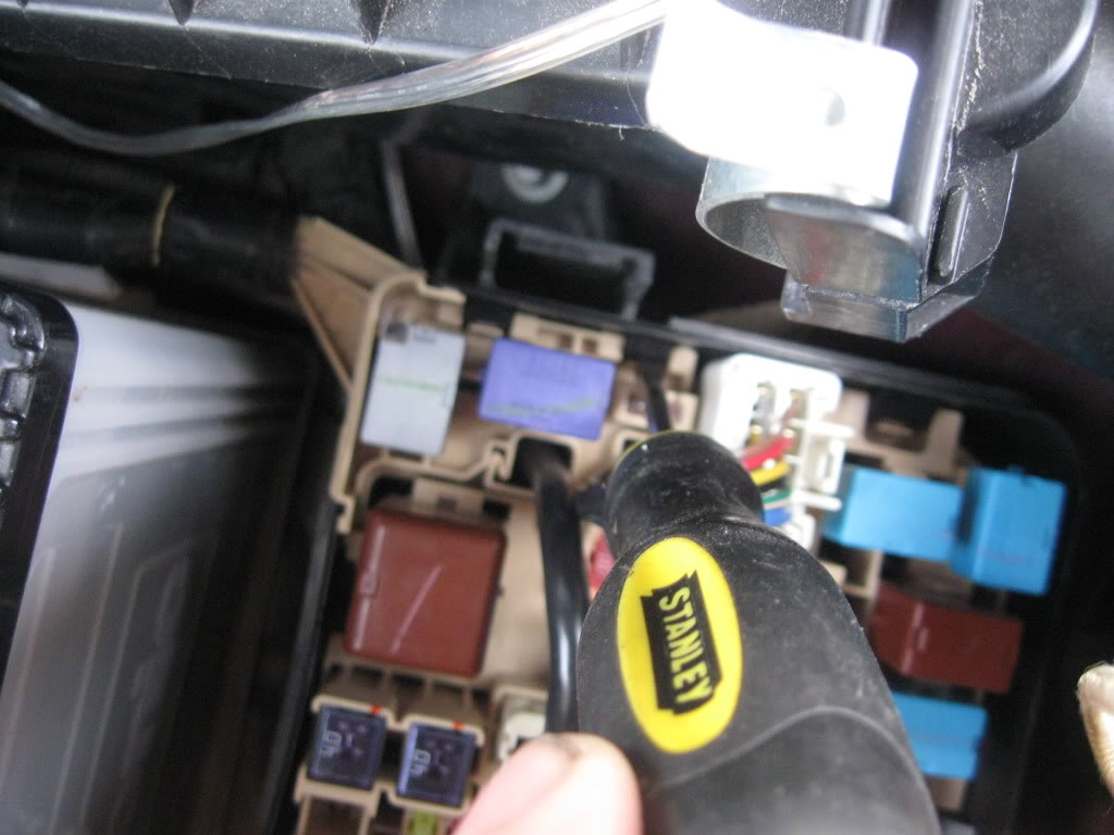
There are three tabs on the large portion of the fuse box, hold those back to be able to pull the large portion up.
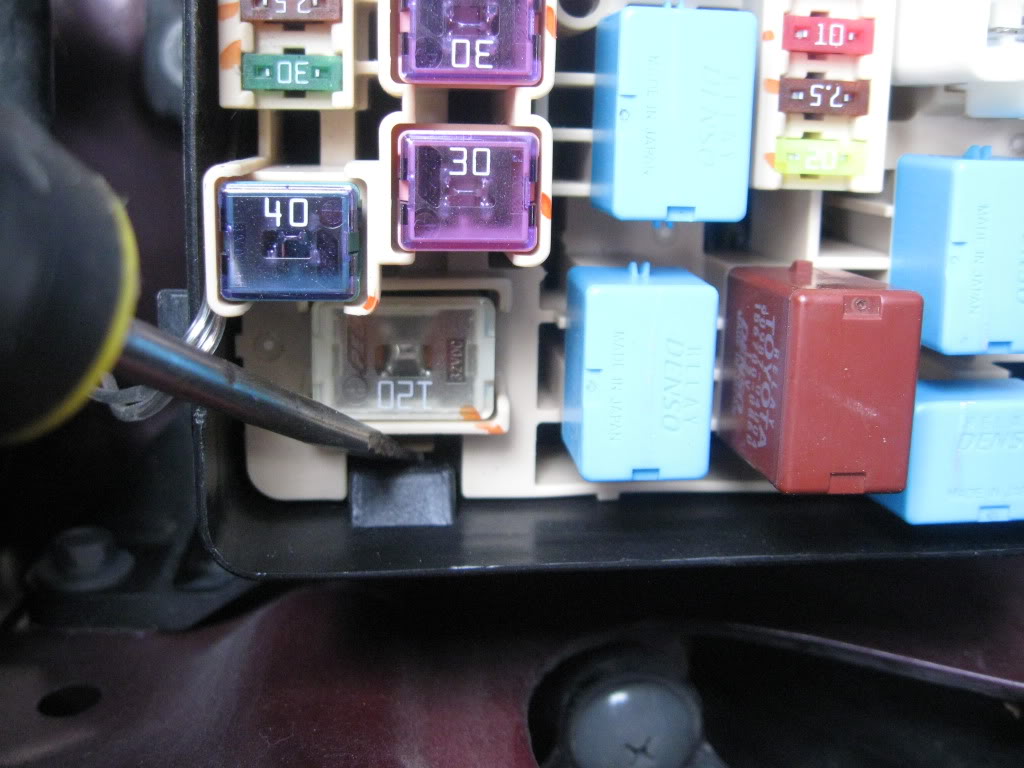
Pull up that portion and lean it back so you can see the wires under the micro fuses.
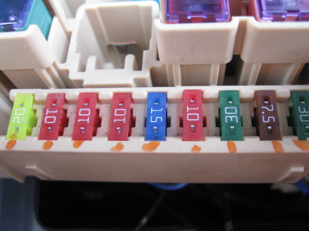
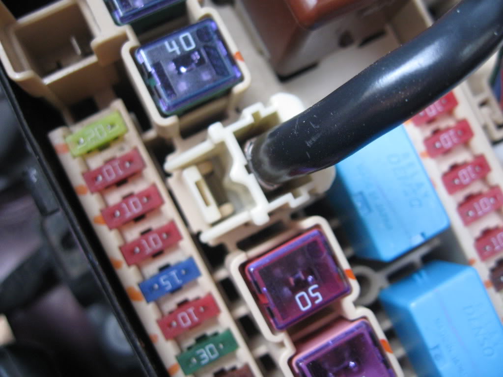
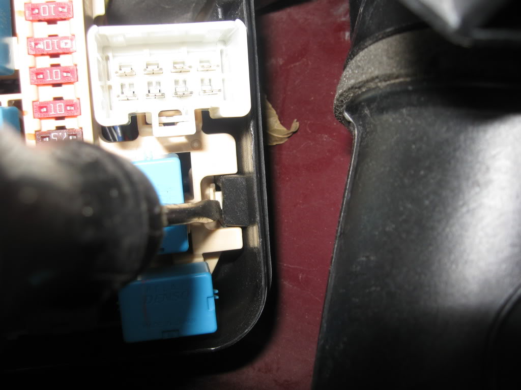
There is a black wire we need to get to that is under the blue 15 amp fuse.
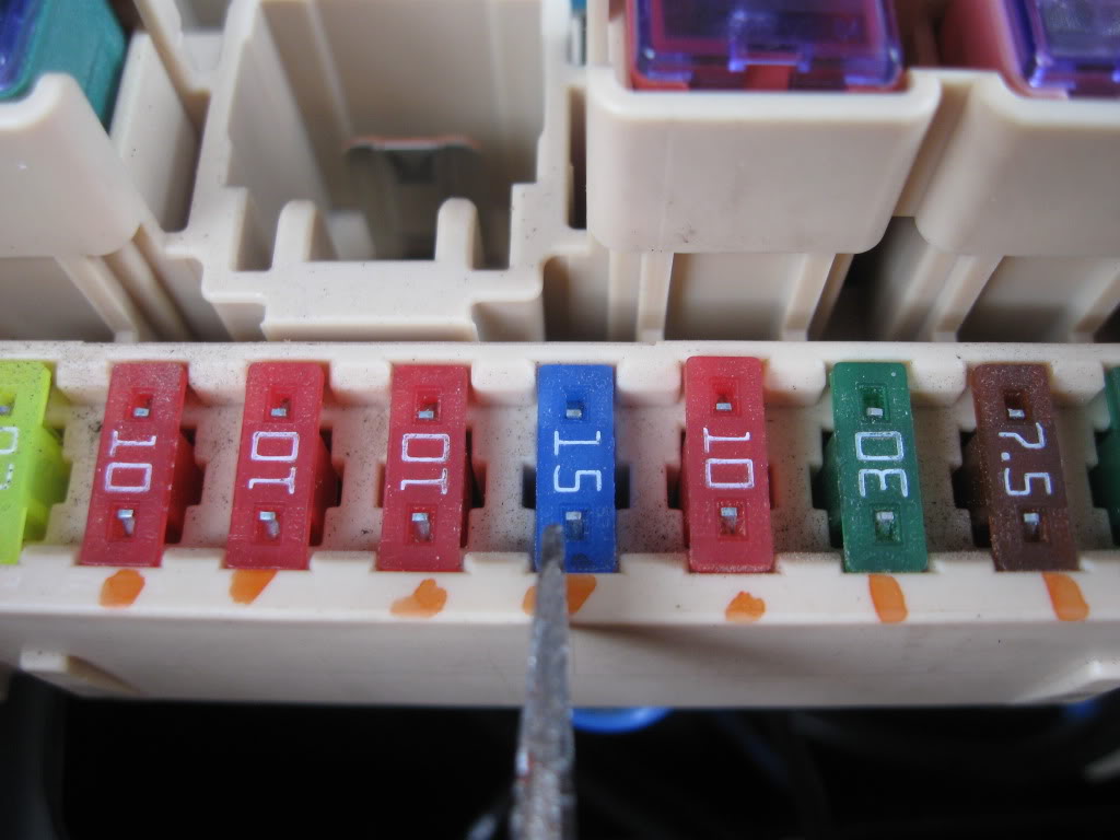
Find that wire and gently pull a little slack towards you, then cut the wire in half but leave enough to work with. You will be dealing with both halves of this wire.
Now have a sip of coffee while your soldering iron heats up.
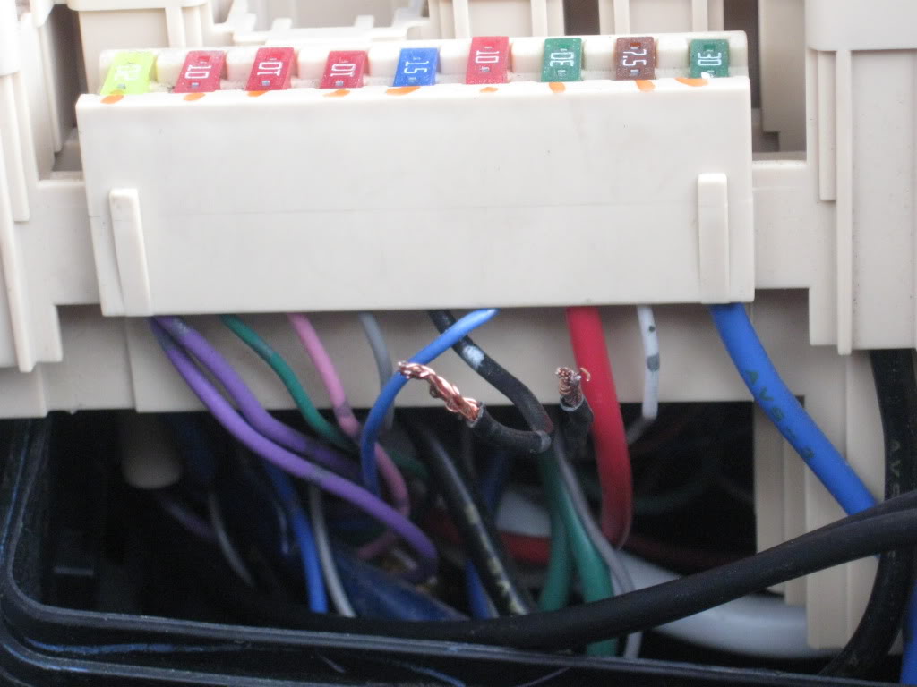
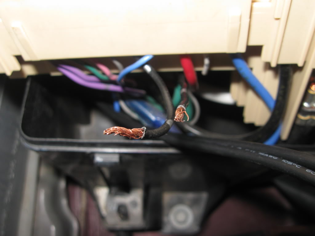
Take one of the wires you pulled into the engine bay (doesnt matter which one) and solder it to one of the wires you just cut.
It was cold so was kinda hard to heat the solder up with this cheap iron i have.
The next step is optional but is good to have done if you ever get rid of the fic or just dont want the 2 step anymore.
Crimp on a female spade connector to the two newly soldered wires and heat shrink over the hole deal.
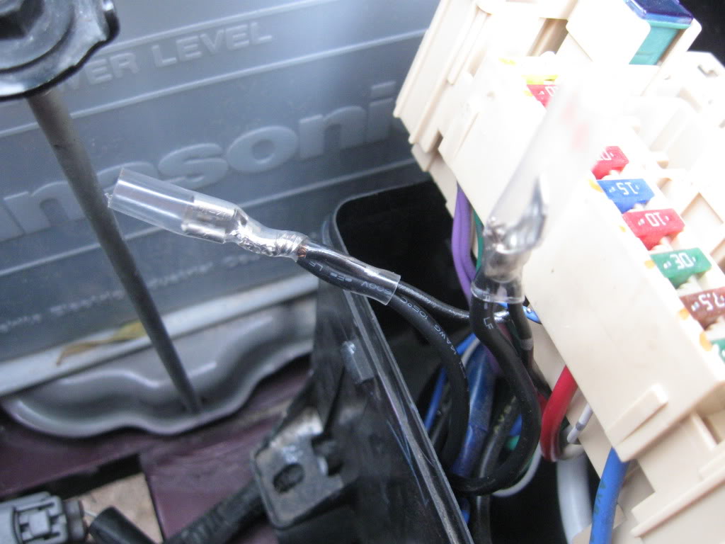
Solder the two remaining wires together and crimp on a male connector. Heat shrink the connection and terminal.
Now stuff the wires down in the fuse box and close everything up. Don't forget to put those two connectors we unplugged back in their homes.
Now we can move on over to the driver side floorboard.
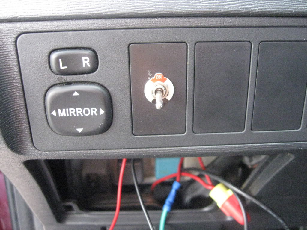
Pull open the kick panel and pop out a switch blank from the dash.
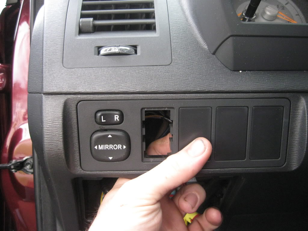
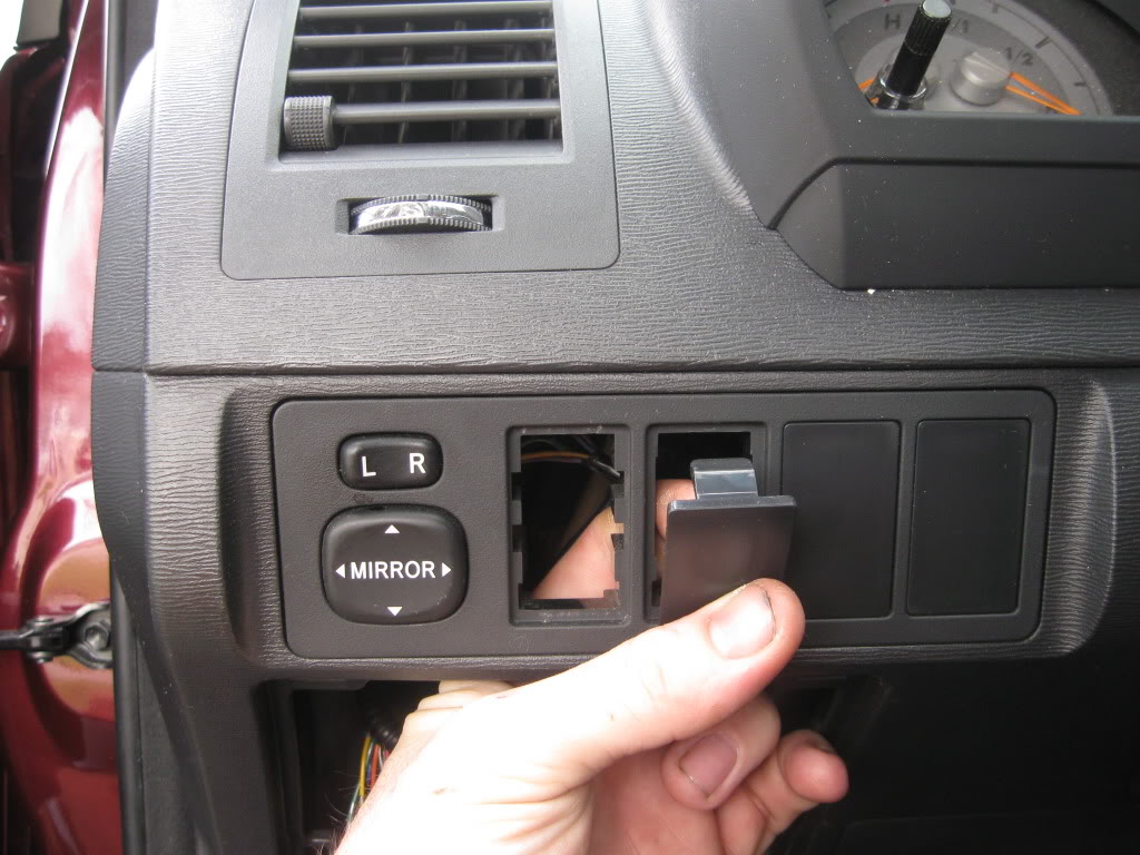
Run your bypass wires up and out of the dash and zip tie them as you go. Also would be a good time to zip tie the other wires out of the way that we ran earlier.
Connect the wires to the toggle switch (spst) and if needed use shrink tube to cover the connections.
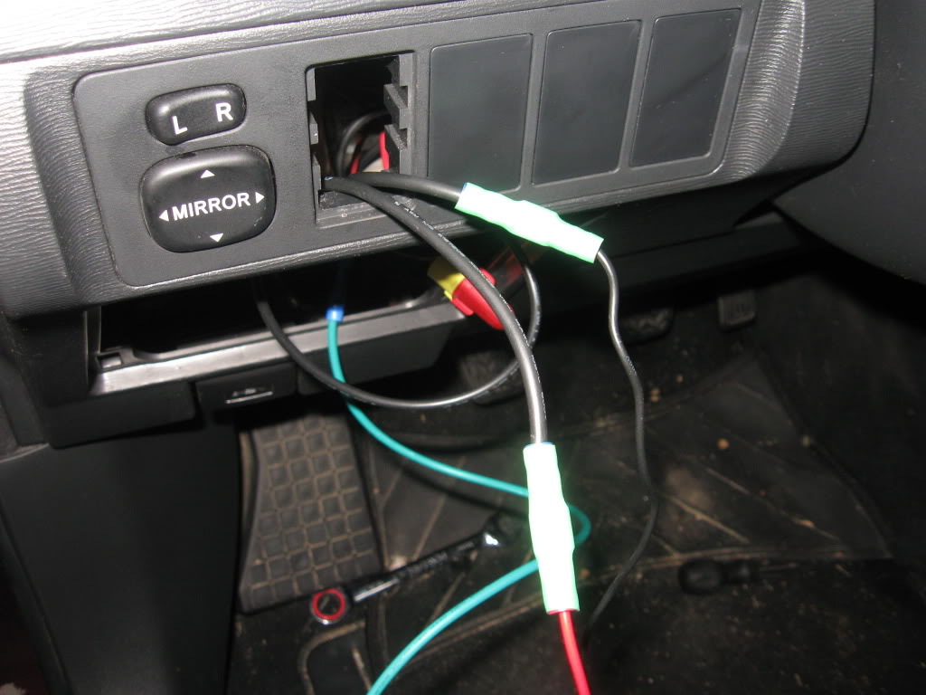
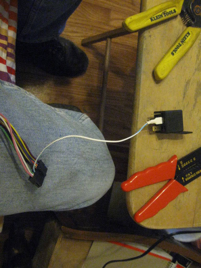
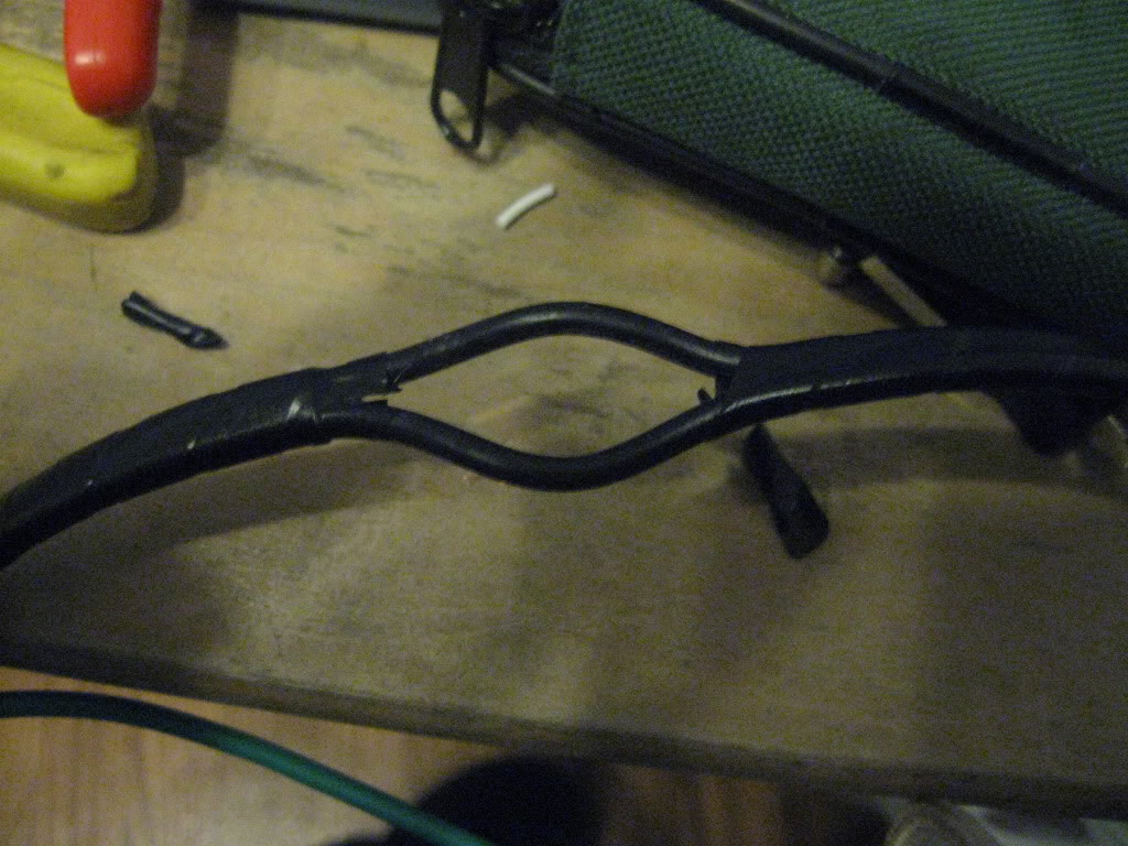
Now here comes the hard part of the whole thing, mounting the limit switch (micro switch). You can either use velcro tape (double sided tape even) and zipties togather to accomplish this or a 1"-1 1/4" thin self taping sheet metal screw. If using the screw then this is of course were the mini drill comes into play.
I used a the screw.
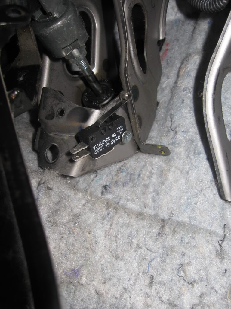
It needs to be mounted so when the pedal goes down it trips the switch.
Now you need a good ground, I used a short piece of wire and crimped a loop on one end and a female spade connector on the other, then I took the loop end to the closest stud. After i pluged in the spade end to the common pin on the limit switch (micro switch).
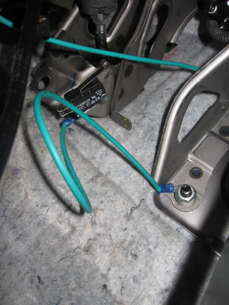
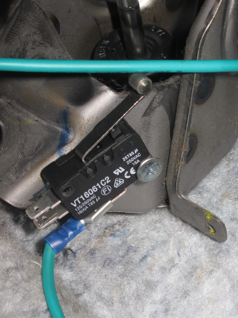
Remember that ground we wired up to the relay that we dropped off in the floorboard, yep we need to route it to the "normally open" pin on the limit switch. Zip tie it as you go.
Feel free to check all your connections with a multi-meter. Also there are other ways of doing this so use your imagination.
----------------------------------------------------------------
The Magic
(set up)
Here we are in the home stretch!!!
Plug in the fic harness, plug in fic, plug in usb to fic, plug in usb to laptop.
Open up the fic program
Click file (on the top tool bar), click on open, click on your current map and click open.
Click on ecu (tool bar at the top) and click connect.
Click on set-up, scroll down to system and click it.
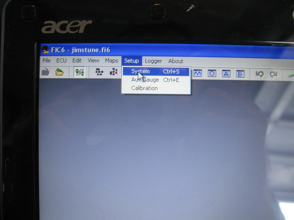
This screen will pop up
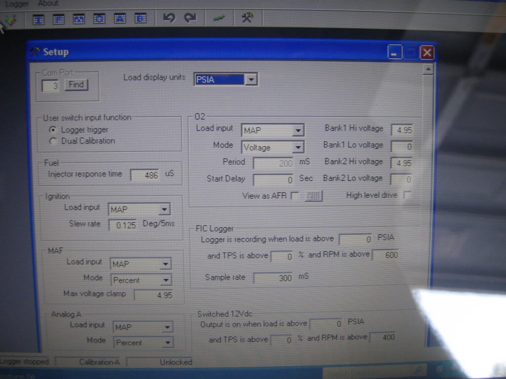
Look at the lower right hand corner of the system screen, you will see a box labeled "Switched 12Vdc".
Set all the parameters in that box to zero.
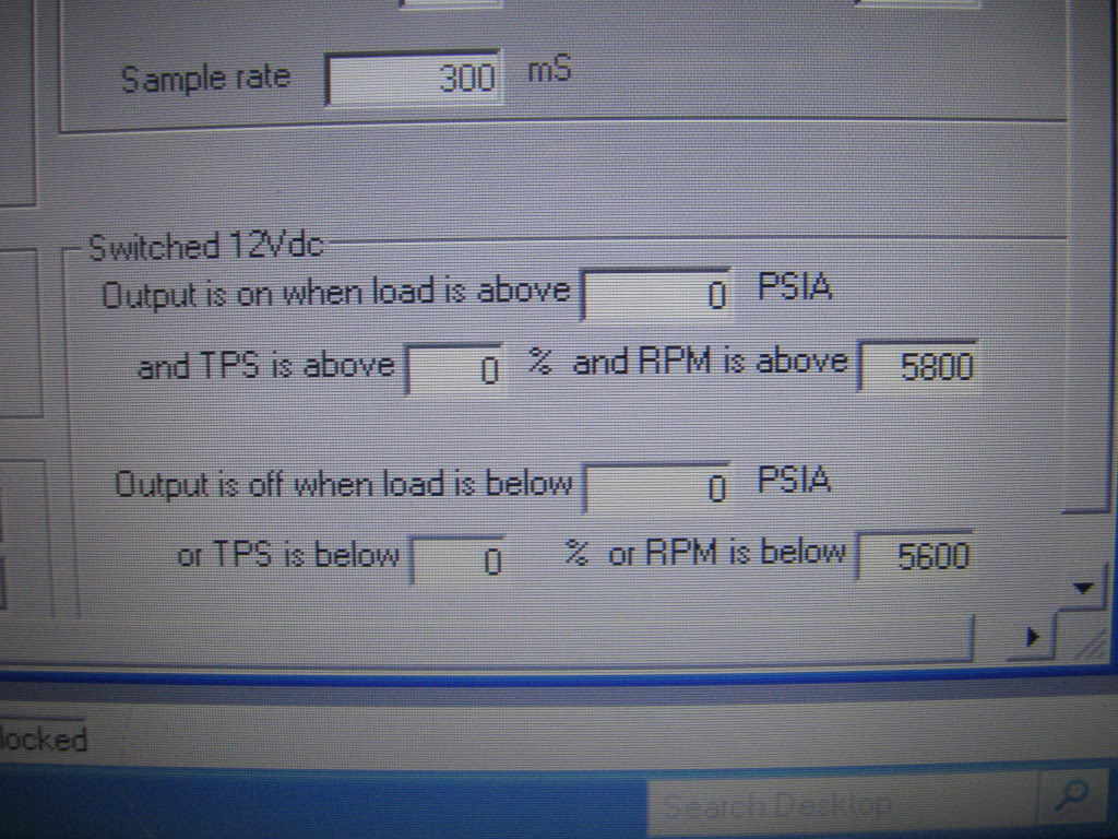
Set the rpm on to desired number and the rpm off to desired number.
On the latest vid i set mine to 4000rpm on and 4000rpm off
----------------------------------------------------------------
The Reward
just some after thoughts.
If I were to replace my exhaust (which it will get replaced soon) and get rid of the cats (which they will go by by after turbo install) you would prolly have the loud poping and fire ***** that are more common to 2step launch control units.
also if anyone is having trouble finding the parts i listed or would like to have their harness prewired pm me
Also in the Vid iv got the bottom part of the stock air box off so it sounds a little beefier if anyone was wondering.
again this is just a test so far.
_____________________________________________________________________
AEM F/IC 2-Step DIY
This is for off-road use only and is done at your own risk!!!
Supplies
AEM Fic
Fic Harness
Shrink tube
Crimp Connectors
14 Gauge Wire and 24 Gauge Wire
Molex Micro-Fit 3.0 Socket Crimp Terminal (This is if you dont have a spare universal harness to pull pins from and using the boomslang pnp harness. If your hardwired using the universal harness your one lucky guy cause youll save yourself some time)
12 Volt 30 Amp Relay (Five pin relay with one "normally closed" contact)
Small Limit Switch (aka Mini snap action switch)
Zip Ties
12 Volt 15 Amp Toggle Switch
Velcro Tape or Double Sided Tape (optional)
Self Taping Sheet Metal Screw (optional)
Red Bull (almost manditory..lol)
Most of this stuff can be found at Fry's electronics except for fic, pnp harness, molex pins. Fic and harness can be found at www.dezod.com and molex pins can be found at www.alliedelec.com .
---------------------------------------------------------------------------
Tools
Crimpers
Stripers
Multi-meter (for checking connections and trouble shooting)
Flat head screw driver
Tiny drill (skill xo, ryobi 4volt driver, etc) (optional)
Philips head screw driver (optional)
Solder
Soldering Iron
Knife
Lighter or heat gun
----------------------------------------------------------------
Pre-wiring
We will start with the relay, take note of the wiring diagram thats on it. Almost all relays have a wiring diagram that will tell you what pins do what.
Break out the relay and find the two pins for the coil. You will need to either pull out a pin from the Fic universal harness or you'll need to grab the 24 gauge wire. Take one end of that wire and crimp on a female spade connector. Heat shrink the wire and connector so nothing can make contact with it from the sides. Plug this wire into one of the pins for the coil on the relay. On my relay this pin is labeled 85.
Take the other end of that wire and crimp on a molex micro-fit 3.0 terminal. If using a wire and terminal pulled from the fic universal harness then no need for crimping a molex terminal on.
Now we need to find pin 16 on the 24 pin connector, on my harness pin 16 is on the top row right next to the green wire.
If still unsure of which pin look through your fic wiring instructions thats on your install CD, it will have a complete pin-out for both connectors that plug into the fic.
Now take that wire we were just dealing with and push it into pin 16 of the 24 pin connector.
It should look like this
Make sure you have pushed it in as far as the others, if it doesnt stay firm in the connector or isnt pushed in far enough you will not have proper contact.
Now move to the one pin for the coil of the relay thats left. Its labeled 86 on my relay. This is were we are going to bring a ground to that will come from the limit switch that will be mounted under the clutch pedal so make sure you cut yourself enough wire to do so. It will roughly take about 10ft of wire to be on the safe side.
Unroll some 14 gauge wire for this and crimp on a female spade connector. Heat shrink it to be safe after its been crimped, plug it into the relay.
Next we will need two long runs of wire roughly 15ft long each. Thes will go from relay to engine bay.
Crimp on one female connector per wire and heat shrink them.
One will be pluged into the common terminal of the relay, on my relay its labeled 30. The other wire needs to be pluged into the relay pin thats a "normally closed" contact. This pin is labeled 87a on my relay.
So far everything should start looking like this
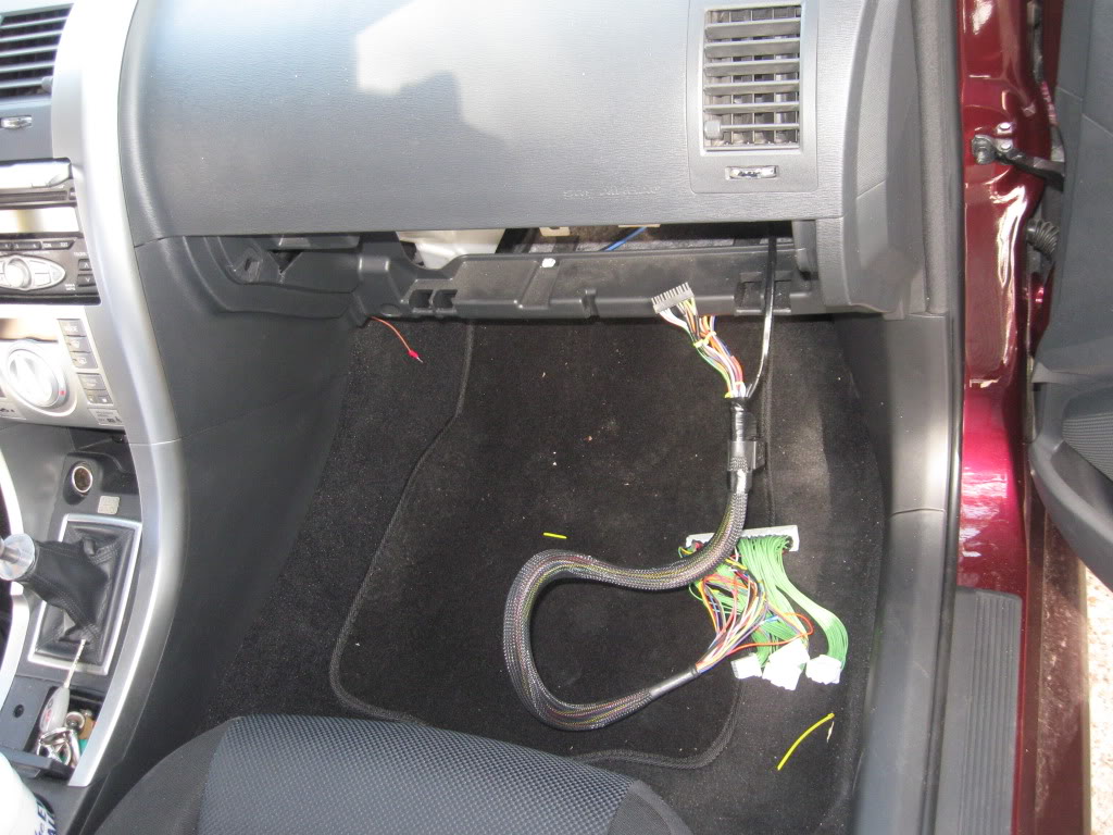
We are almost done with the relay, just need to tape it up to the Fic pnp harness (or mount it someplace in the glove box later)
Now we need to splice into the wire thats connected to pin 30 on my relay with another 14 gauge wire thats roughly 5ft long depending on where you tap into. this is one is for the bypass switch (12 volt toggle switch) so you can activate or deactivate the 2 step. Then you will need to take another 5ft long piece of wire and tap into the wire coming from pin 87a on my relay. This too is for the bypass switch. I suggest to make your connections by peeling back a little insulation on the two wires coming from the relay and soldering each bypass wire but a tap (suitcase) connector could be used.
Your just about done with the pre-wire just need to tape up or heat shrink the wires to keep them neat and together.
----------------------------------------------------------------
Wiring
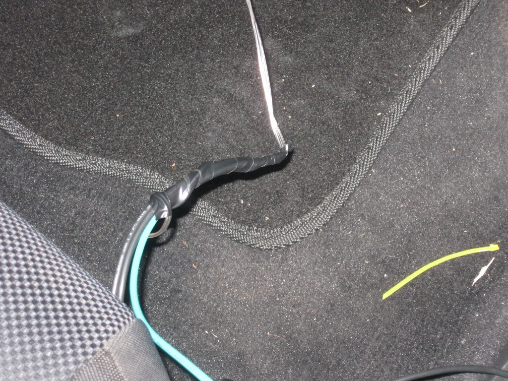
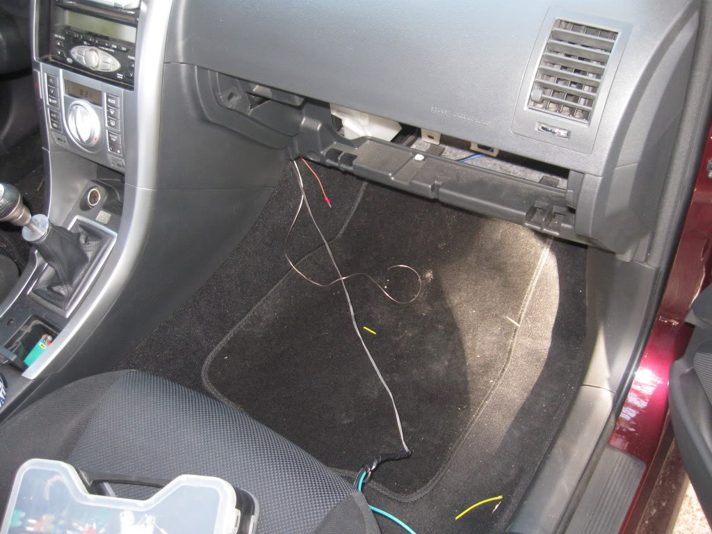
Now that the harness is ready its time to run the wires through the glove box. You can use a coat hanger to fish the wire through to the driverside floor board if it helps. I had the test wires already ther so i used them to pull in the new wires.
Now we are going to drop off the two wires for the bypass switch and the ground at the driver-side floor board, then take the two wires connected to pin 30 & 87a and run them through the fire wall. You can run them through the large grommet located above the pedals. Again I used my test wires to help pull them through the fire wall.
You will need to pull them all the way to the fuse box in the drivers side of the engine bay.
Pop the cover off of the fuse box.
Thes two connectors will need to be disconnected for the moment.
Disconnect battery.
There are two tabs that hold in the small portion of the fuse box that will need to be pulled back to release it. This is where the flat head screw driver comes into play. Hold the tab back with the flat head and gently pull up on the small section. Keep holding it up while you swap over to the other tab and do the same thing.
Pull out the small section of the fuse box and place it out of the way.
next unplug the brown cube relay.
There are three tabs on the large portion of the fuse box, hold those back to be able to pull the large portion up.
Pull up that portion and lean it back so you can see the wires under the micro fuses.
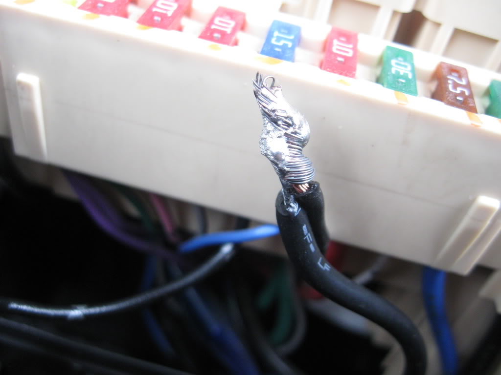
There is a black wire we need to get to that is under the blue 15 amp fuse.
Find that wire and gently pull a little slack towards you, then cut the wire in half but leave enough to work with. You will be dealing with both halves of this wire.
Now have a sip of coffee while your soldering iron heats up.
Take one of the wires you pulled into the engine bay (doesnt matter which one) and solder it to one of the wires you just cut.
It was cold so was kinda hard to heat the solder up with this cheap iron i have.
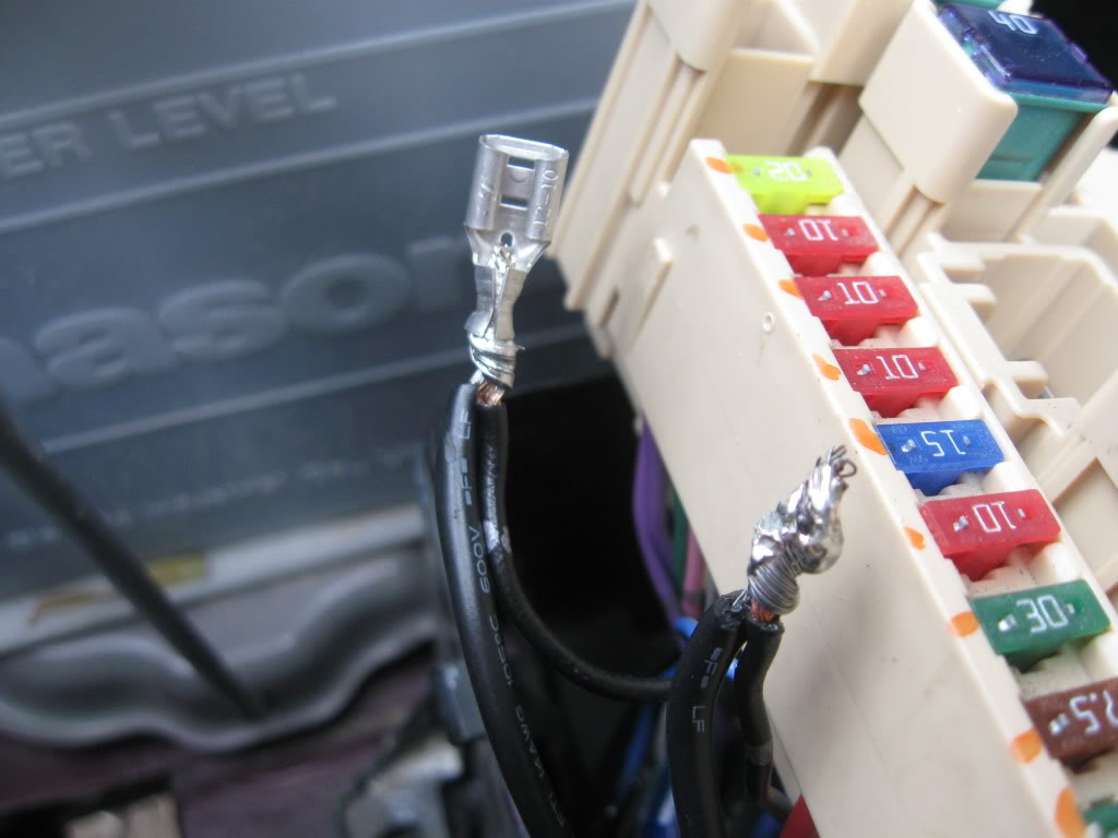
The next step is optional but is good to have done if you ever get rid of the fic or just dont want the 2 step anymore.
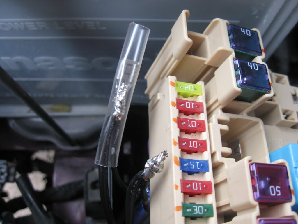
Crimp on a female spade connector to the two newly soldered wires and heat shrink over the hole deal.
Solder the two remaining wires together and crimp on a male connector. Heat shrink the connection and terminal.
Now stuff the wires down in the fuse box and close everything up. Don't forget to put those two connectors we unplugged back in their homes.
Now we can move on over to the driver side floorboard.
Pull open the kick panel and pop out a switch blank from the dash.
Run your bypass wires up and out of the dash and zip tie them as you go. Also would be a good time to zip tie the other wires out of the way that we ran earlier.
Connect the wires to the toggle switch (spst) and if needed use shrink tube to cover the connections.
Now here comes the hard part of the whole thing, mounting the limit switch (micro switch). You can either use velcro tape (double sided tape even) and zipties togather to accomplish this or a 1"-1 1/4" thin self taping sheet metal screw. If using the screw then this is of course were the mini drill comes into play.
I used a the screw.
It needs to be mounted so when the pedal goes down it trips the switch.
Now you need a good ground, I used a short piece of wire and crimped a loop on one end and a female spade connector on the other, then I took the loop end to the closest stud. After i pluged in the spade end to the common pin on the limit switch (micro switch).
Remember that ground we wired up to the relay that we dropped off in the floorboard, yep we need to route it to the "normally open" pin on the limit switch. Zip tie it as you go.
Feel free to check all your connections with a multi-meter. Also there are other ways of doing this so use your imagination.
----------------------------------------------------------------
The Magic
(set up)
Here we are in the home stretch!!!
Plug in the fic harness, plug in fic, plug in usb to fic, plug in usb to laptop.
Open up the fic program
Click file (on the top tool bar), click on open, click on your current map and click open.
Click on ecu (tool bar at the top) and click connect.
Click on set-up, scroll down to system and click it.
This screen will pop up
Look at the lower right hand corner of the system screen, you will see a box labeled "Switched 12Vdc".
Set all the parameters in that box to zero.
Set the rpm on to desired number and the rpm off to desired number.
On the latest vid i set mine to 4000rpm on and 4000rpm off
----------------------------------------------------------------
The Reward
just some after thoughts.
If I were to replace my exhaust (which it will get replaced soon) and get rid of the cats (which they will go by by after turbo install) you would prolly have the loud poping and fire ***** that are more common to 2step launch control units.
also if anyone is having trouble finding the parts i listed or would like to have their harness prewired pm me
Last edited by MR_LUV; Oct 31, 2017 at 05:21 AM. Reason: thread revived to provide some pics to previous OP thread


Nice work man, can't wait for more details. I have been so busy with my engine build I haven't even gotta a change to mess with anything more than fuel and o2 maps in the fi/c let alone devise a launch control mechanism 


Thread Starter
Joined: Feb 2008
Posts: 11,271
From: Houston, TX
I been very excited about doing this mod for the last month and finally got an fic. been waiting on ups to get me that lost package from yesterday that has the female pins for the fic and they still havent gotten here yet. Im starting to hate ups. anyways there is a few ways of doing this via the fic and i want to try other things first before a diy on it. also need to confirm the reliability and consistancy of this 2step.
Thread Starter
Joined: Feb 2008
Posts: 11,271
From: Houston, TX
it doesnt but it gives you outputs to use that can be configured to do it. there are 3 user outputs and two of those are maps (analog a and B) that most dont know about or dont care about. the possibilities are endless using thes outputs. Iv already done a shift light using the fic using the 12volt switched output, that diy can be found on the fic setup sticky above.
Thread Starter
Joined: Feb 2008
Posts: 11,271
From: Houston, TX
^^I thought about that but my plans didnt include using the fic though. I could though configure the fic to be a boost controller, i would have to get a cylinoid though. it will be hard though to get it in the butter zone.

