Aftermarket LED tail light MOD (diy sorta)
 07-25-2008, 04:29 AM
#81
Senior Member
SL Member
Thread Starter

Join Date: Jan 2007
Posts: 2,192
Originally Posted by PregoRollerSkate
Can you not take the yellow and black wire and just tap them into the existing led wires?

 01-28-2009, 04:10 AM
#85
Senior Member
SL Member

Join Date: Mar 2008
Location: BFE SoCal
Posts: 618
I would use this if I were to do this mod.
http://www.jpcycles.com/productdetai...&page=&search=
I know it is expensive but it doesn't heat up like the resistors your using causing melted plastic or peeled paint, or worse a fire.
I used this product on my HD as I have a full LED conversion on my bike and had to deal with a "lamp out" idiot light and hyper flashing.
 01-30-2009, 02:00 AM
#87
Senior Member
SL Member
Thread Starter
Join Date: Jan 2007
Posts: 2,192
Originally Posted by Eltaco
I would use this if I were to do this mod.
http://www.jpcycles.com/productdetai...&page=&search=
I know it is expensive but it doesn't heat up like the resistors your using causing melted plastic or peeled paint, or worse a fire.
I used this product on my HD as I have a full LED conversion on my bike and had to deal with a "lamp out" idiot light and hyper flashing.
http://www.jpcycles.com/productdetai...&page=&search=
I know it is expensive but it doesn't heat up like the resistors your using causing melted plastic or peeled paint, or worse a fire.
I used this product on my HD as I have a full LED conversion on my bike and had to deal with a "lamp out" idiot light and hyper flashing.
to anyone running LED tails... put this mod on your list! i promise you the results are awesome in person on the road :-)
01-30-2009, 06:43 AM
#88
Senior Member
SL Member
Join Date: Mar 2008
Location: BFE SoCal
Posts: 618
Snow has inspired me to attempt this mod with my tC's TYC tail lights. I will have the brake array flash with my LED ambers.
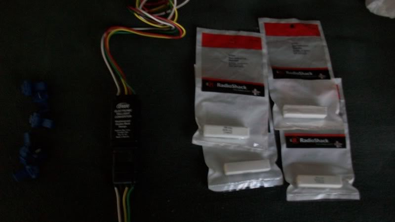
Also when I did my LED mod to my Harley
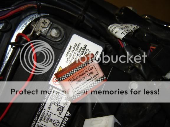
I originally used these as load resistors as the stock Harley light controller has a bulb out warning and hyper flash.
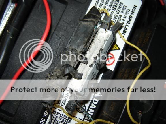
When they melted the heat shrink and spiral wrap that I had used to secure them I replaced them with these units.
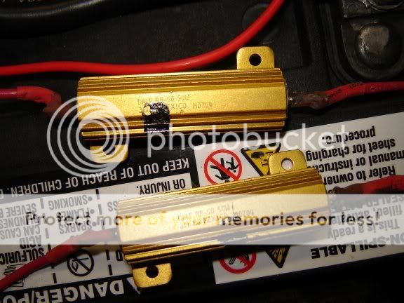
As you can see heat was still an issue as the ends where the wires connect to the resistor the heat shrink fried off.
Keep in mind these were only temporary use when the turn signals are in use.
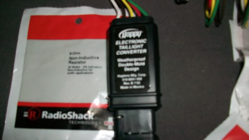
I then upgraded to the flasher / converter / load resistor I posted earlier.
The best feature about this solid state load balance device is it makes the turn signals come on with the brake. I am sure your asking as to how this could be used to modify LED aftermarket tail lights for your xB, tC, xA, or xD. Think of your center mount third brake light as the brake light on a motor cycle and your tail lights as the turn signals on a motor cycle.
Just to show how obsessed I am with LED's if you notice in the animations I posted, I even have LED's in the fender tip lights and including my gas gauge.
I desperately need a 12 step program to cure my LED addiction.
Once again,
Snow. thank you for an awesome DIY write up!
Also when I did my LED mod to my Harley
I originally used these as load resistors as the stock Harley light controller has a bulb out warning and hyper flash.
When they melted the heat shrink and spiral wrap that I had used to secure them I replaced them with these units.
As you can see heat was still an issue as the ends where the wires connect to the resistor the heat shrink fried off.
Keep in mind these were only temporary use when the turn signals are in use.
I then upgraded to the flasher / converter / load resistor I posted earlier.
The best feature about this solid state load balance device is it makes the turn signals come on with the brake. I am sure your asking as to how this could be used to modify LED aftermarket tail lights for your xB, tC, xA, or xD. Think of your center mount third brake light as the brake light on a motor cycle and your tail lights as the turn signals on a motor cycle.
Just to show how obsessed I am with LED's if you notice in the animations I posted, I even have LED's in the fender tip lights and including my gas gauge.
I desperately need a 12 step program to cure my LED addiction.
Once again,
Snow. thank you for an awesome DIY write up!
01-30-2009, 11:34 PM
#89
Senior Member
SL Member

Join Date: May 2005
Location: L.A.,CA
Posts: 701
^^^ That is really really cool. I was trying to find those gold resistors, where did you get them(and what do they call those type?).
I am running Snow's mod with the regular white resistors. I have no problem with them, but they do get pretty hot. They are stuck to the backside of the metal where the taillight is secured to the body with double sided tape. So far, so good.
If you have the time, can you post a quick diagram of how this adapter you are using is hooked up. Thanks.
01-31-2009, 12:01 AM
#91
Senior Member
SL Member
Thread Starter
Join Date: Jan 2007
Posts: 2,192
Originally Posted by Eltaco
I am sure your asking as to how this could be used to modify LED aftermarket tail lights for your xB, tC, xA, or xD. Think of your center mount third brake light as the brake light on a motor cycle and your tail lights as the turn signals on a motor cycle.
Once again,
Snow. thank you for an awesome DIY write up!
Once again,
Snow. thank you for an awesome DIY write up!
please help me out to understand though how this module will work as what i was trying to accomplish? i see how the unit adds brake function to turn signals but you said think of our 3rd brake light as the center light on your cruiser but they aren't the same. our 3rd brake lights do not come on as parking lights. i'm not seeing how you would get a parking light function from the tails. i'm just curious how you would propose to wire this to your vehicle. i mean what exact wires from your harness would you run through this module and how you connect the output wires to where.
i see a benefit which is not using resistors in the turn signal circuit but you're still going to need them in your braking circuit.
i guess what i'm saying is i just don't see how it will work and in what way it benefits using it for $70 over the towing module for $15. do you have a wiring diagram by chance?? i'm not saying you are wrong or anything i just want to know how it will work if you could please help me out.
if you do decide to use the towing module though definitely get rid of your plug&play LED bulbs in your turn signals currently on the TC. those things are crap man. that's the number one thing i tell people not to do that want LED lighting. they don't put out nearly enough lumens especially for daytime use.
01-31-2009, 02:58 AM
#92
Senior Member
SL Member
Join Date: Mar 2008
Location: BFE SoCal
Posts: 618
I could be way off base, as I don't have the wiring diagram anymore from the unit I already have. My theory is this: my tC does not have any type of "bulb out" warning etc. Based on your DIY on the xB there is an issue with your cruise control and tail light warning lights, hyperflash etc. similar to my HD. With that being said, stock xB brake lead would go to the module I posted, stock xB left and right turn signal lead would go to their respective input on the module. Now you would take the left and right output from the module to their respective LED tail lights on the xB, now you wouldn't want to hook up the brake light output from the module to anything, just leave it open or taped off. Now if my theory is correct the module is designed to return a signal to your vehicle's brake, right, and left turn lead that there is a working bulb in place.
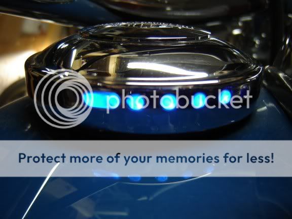
And your right, the 48 SMT LED array in my TYC turn's is only about 80% as bright as incandescent but they look so nice. Now if I do your mod to them and the red LED's from the TYC's flash with the amber's, the combined brightness should be safe.
Sample of how bright the amber's are in relation to the red's in the TYC's.
01-31-2009, 05:01 AM
#93
Senior Member
SL Member
Thread Starter
Join Date: Jan 2007
Posts: 2,192
that's the thing, they all look amazing in the dark. especially that close to a wall. even at night the instantaneous on/off takes the attention away from how much dimmer they are. when you are driving around on a sunny day, people behind you are going to barely be able to see your turn signals. if they are looking for them they will see them, but you don't want that. my theory is LED is only an upgrade when it out performs a regular bulb. i retrofitted an entire set of stock tail lights just to throw them away because the lenses destroyed my daytime light output. it was probably my most epic LED project fail. all that time for nothing.
i would test your idea of combining the red-orange and amber signaling at the same time too. i'm picturing that as just looking like a colorful mess especially being so close together. just keep it clean man, remove the turn signals (or add them as more backup light) and run the LED arrays as your park/brake/signals with the towing module. you don't even need resistors in your brake circuits as the TC is programmed for an LED 3rd brakelight.
this mod also applies to just about every new car on the road now with LED park/brake and filament signals by the way. ditch the filament signals and use the LED arrays with correct optics for proper lumen throw.
come on, i need a TC guy to jump on board here. don't have one yet. ya gotta do it :-)
10-07-2009, 09:08 PM
#95
Senior Member
SL Member
Join Date: May 2005
Location: L.A.,CA
Posts: 701
You can do it. I had never done anything like this before. It took me all day, but I was able to get everything working correctly. Cutting and splicing the wires made the whole thing look like a pasta dish while working on it, but if you take your time, you can do it. Keep the wiring diagram next to you.
The resistors do get hot, but by keeping them away from the plastics and anything else that might melt is fairly easy. Just make sure you stick them against the body(metal) with a double sided tape.
The resistors do get hot, but by keeping them away from the plastics and anything else that might melt is fairly easy. Just make sure you stick them against the body(metal) with a double sided tape.
10-10-2009, 01:28 AM
#98
Senior Member
SL Member
Join Date: Aug 2007
Location: DubV
Posts: 1,267
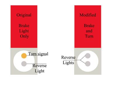
I need to study this diagram because I'm so confused. I thought the light bulbs were just going to be switched to reverse lights and the brake light was going to dual as a signal?
10-10-2009, 06:53 AM
#99
Senior Member
SL Member
Join Date: May 2005
Location: L.A.,CA
Posts: 701
Zman, you are correct. The original turn light bulb and reverse light bulb will be modified into all reverse light bulbs.
The brake light (LED array) will serve as both a turn signal and a brake signal. Hope this helps.
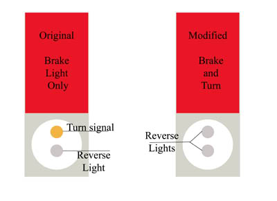
The brake light (LED array) will serve as both a turn signal and a brake signal. Hope this helps.
11-16-2009, 09:06 PM
#100
Senior Member
SL Member
Join Date: Aug 2007
Location: DubV
Posts: 1,267
Last edited by Zman; 11-16-2009 at 09:13 PM.