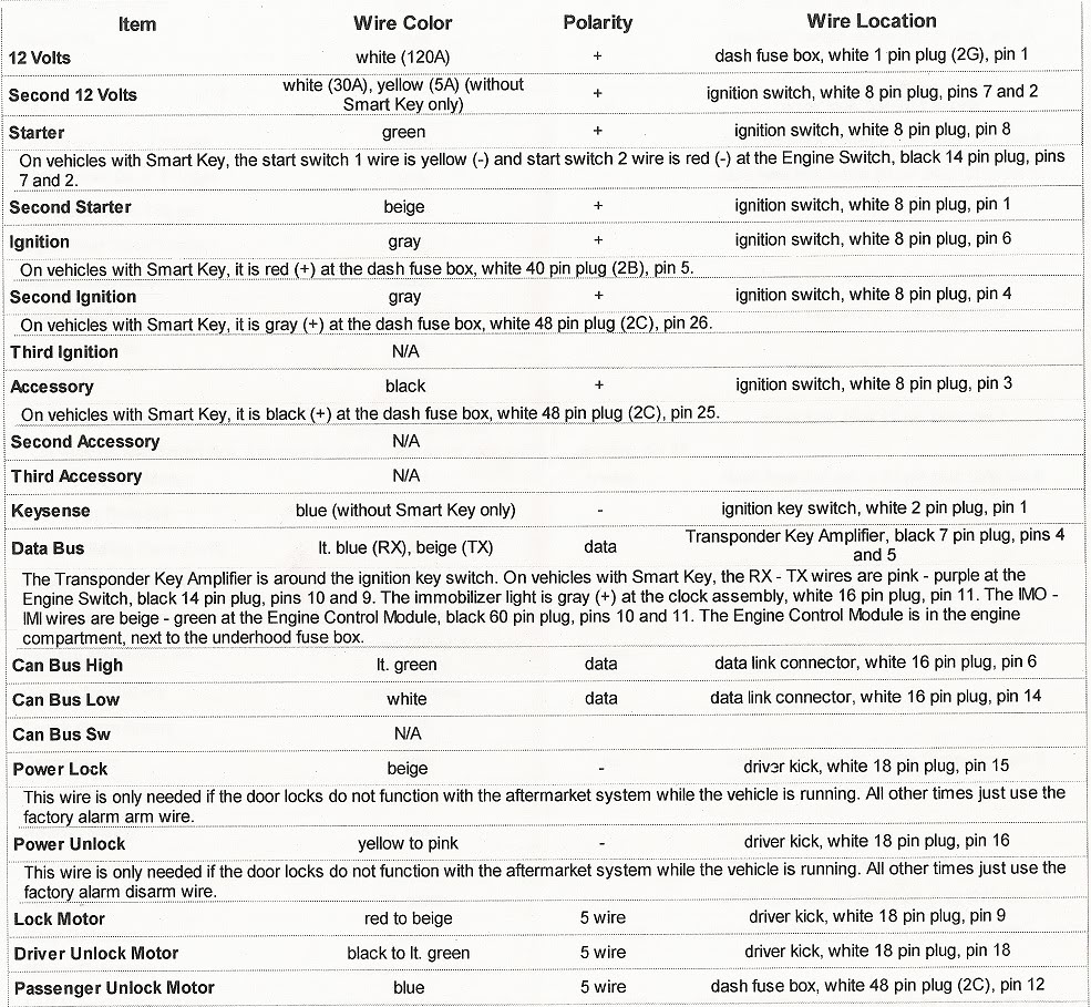
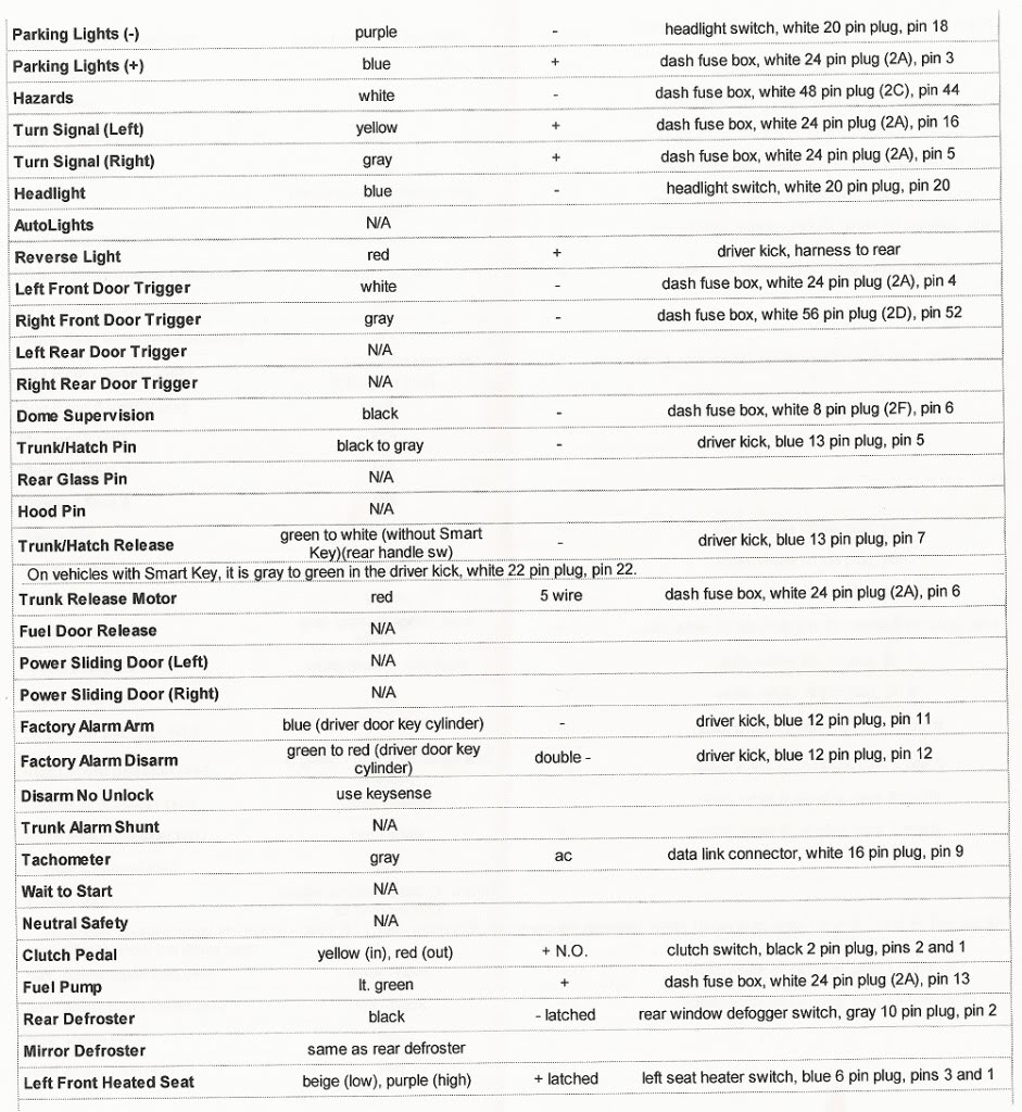
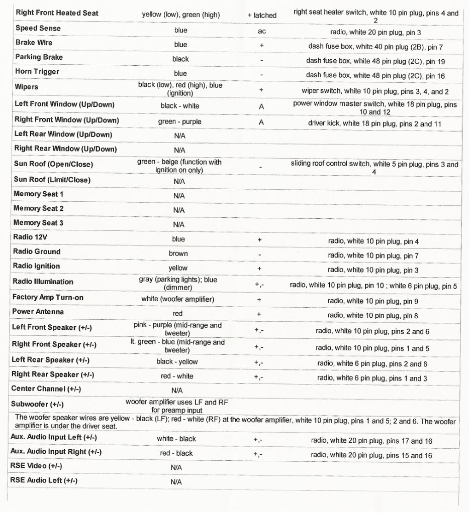
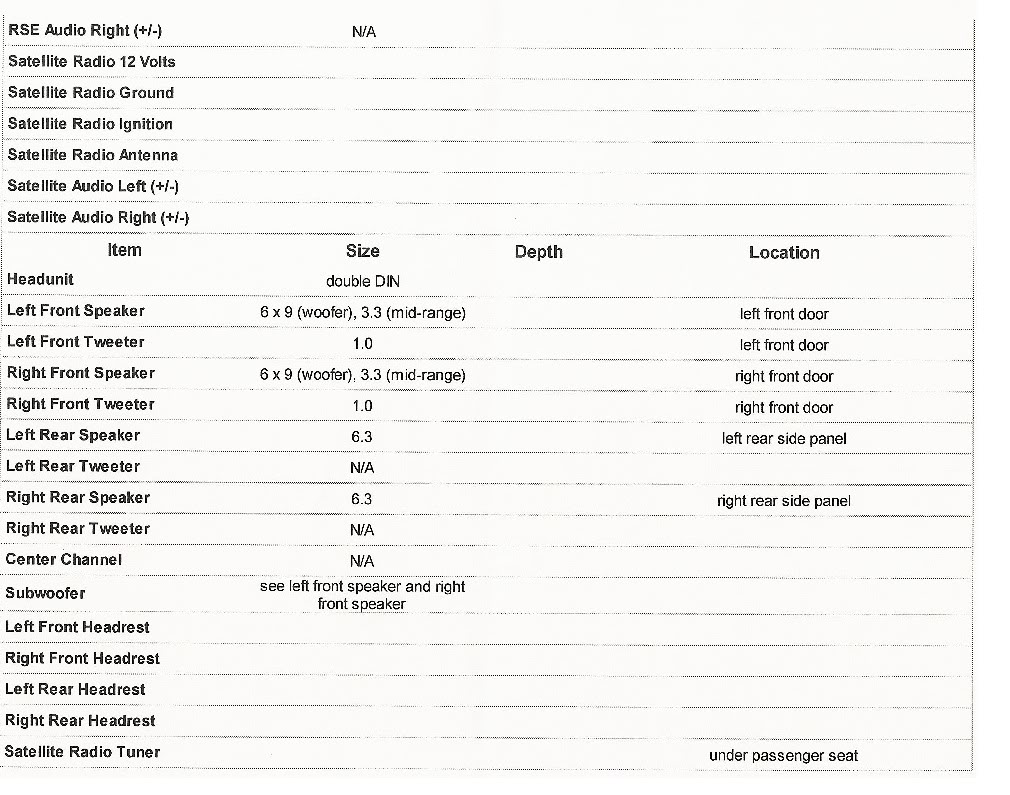
2nd Gen tC Wiring Diagram


 10-18-2011, 04:48 PM
#3
Senior Member
SL Member

Join Date: Feb 2011
Location: Dallas/Houston, TX
Posts: 1,018
im sure its on here but im not sure which one it is.
◄◄Click Here to Add your Vehicle to Garage
on the driver side window switches. for the lights. what color are the +/- wires for that?
◄◄Click Here to Add your Vehicle to Garage
on the driver side window switches. for the lights. what color are the +/- wires for that?
 12-03-2011, 04:36 AM
#7

That wiring is provided by directed electronics (clifford, viper, etc) for installers doing car audio, video, alarms & remote starts. I use it nearly everyday at work and the only way to have access to it is to be a directed dealer. You should feel fortunate this was posted for your guys as it is essentially all you need to install just about anything (short of performance products).
If you want some really legit wiring guides get alldata, I have it for work and its the shiznit. And if you are truly good at wiring all you need is some know how and a DMM.
I posted one of these for xb2 thread.
If you want some really legit wiring guides get alldata, I have it for work and its the shiznit. And if you are truly good at wiring all you need is some know how and a DMM.
I posted one of these for xb2 thread.
01-12-2012, 07:21 PM
#8
FYI, the smart key wire colors are correct but will not work for remote starting. I will be trying some different wires next weeks on a RS7.
Do not use the wires listed for remote starting with smart key listed on this sheet.
Do not use the wires listed for remote starting with smart key listed on this sheet.
 10-25-2012, 02:35 AM
#11
Senior Member
SL Member

Join Date: Jun 2012
Location: PA
Posts: 630
10-26-2012, 02:24 AM
#12
Senior Member
SL Member
Join Date: Nov 2011
Location: Maplewood, MN
Posts: 187
11-05-2012, 11:17 AM
#13
Senior Member
SL Member

Join Date: Jan 2005
Location: Marshfield, MO
Posts: 173
What would I tap into and/or need to have the reverse lights and front parking lights come on when I unlock the car?
Would think just tap into the front or center dome lights but don't want the exterior lights to come on if I am driving and need to turn the dome light(s) on which would mostly be the front one. Would I even need to add a fuse if all said lights are LED?
Would this even be possible?
Would think just tap into the front or center dome lights but don't want the exterior lights to come on if I am driving and need to turn the dome light(s) on which would mostly be the front one. Would I even need to add a fuse if all said lights are LED?
Would this even be possible?
02-27-2013, 09:26 PM
#14
Junior Member
SL Member

Join Date: Feb 2013
Location: CA
Posts: 14
Ok i know this is a extreeeeeeeeemly old thread but i need help and i can't find answers anywhere. Seeing as the original poster of this seams to have a wiring diagram i was wondering if someone could give me info on the steering wheel control plug wires for a 2011 TC. I purchased a head unit that has a universal steering wheel control function, you tap into three wires and use the built in programming function on the unit to assign the keys to their respective functions.
The wires on the head unit are as follows:
Steering wheel GND
Steering Wheel Key 1
Steering Wheel Key 2
Any info would be great. I contacted the manufacturer but all they could say was that i need to make sure it is an "AD conversion" type setup as opposed to a CANBUS type. I have no idea what type my car is...
Thanks in advance everyone!
02-28-2013, 03:00 AM
#15
Senior Member
SL Member

Join Date: Oct 2012
Location: Ontario, Canada
Posts: 229
Ok i know this is a extreeeeeeeeemly old thread but i need help and i can't find answers anywhere. Seeing as the original poster of this seams to have a wiring diagram i was wondering if someone could give me info on the steering wheel control plug wires for a 2011 TC. I purchased a head unit that has a universal steering wheel control function, you tap into three wires and use the built in programming function on the unit to assign the keys to their respective functions.
The wires on the head unit are as follows:
Steering wheel GND
Steering Wheel Key 1
Steering Wheel Key 2
Any info would be great. I contacted the manufacturer but all they could say was that i need to make sure it is an "AD conversion" type setup as opposed to a CANBUS type. I have no idea what type my car is...
Thanks in advance everyone!
The wires on the head unit are as follows:
Steering wheel GND
Steering Wheel Key 1
Steering Wheel Key 2
Any info would be great. I contacted the manufacturer but all they could say was that i need to make sure it is an "AD conversion" type setup as opposed to a CANBUS type. I have no idea what type my car is...
Thanks in advance everyone!
02-28-2013, 12:06 PM
#16
Junior Member
SL Member
Join Date: Feb 2013
Location: CA
Posts: 14
Good point...
Its an Eonon G2103V
The info can be found here:
http://www.eonon.com/Car-GPS/2-Din-C...VD/G2103V.html
Any help would be much appreciated!
Its an Eonon G2103V
The info can be found here:
http://www.eonon.com/Car-GPS/2-Din-C...VD/G2103V.html
Any help would be much appreciated!
02-28-2013, 09:09 PM
#17
Junior Member
SL Member
Join Date: Feb 2013
Location: CA
Posts: 14
I figured it out, so for anyone else who is looking for the same answer i will list it below, it uses the same pin-out as most toyotas since 1980.
anyway, the wires are as follows:
GRND is pin 6 if looking at the pin side of the 20 pin white connector,
Key 2 is pin 7
Key 3 is pin 8
I found the pin-out here:
http://www.castulucci.com/projects/c...ors/index.html
Thanks everyone!
anyway, the wires are as follows:
GRND is pin 6 if looking at the pin side of the 20 pin white connector,
Key 2 is pin 7
Key 3 is pin 8
I found the pin-out here:
http://www.castulucci.com/projects/c...ors/index.html
Thanks everyone!
08-05-2013, 08:12 PM
#18
Junior Member

Join Date: Aug 2013
Location: Huntsville, AL
Posts: 10
I Finally Finished my Sub Install on my 2014 Scion TC (*W/O BeSpoke)
Here are the wires to use for a Line Output Converter
Left Rear Speaker Positive Wire (+): Black
Left Rear Speaker Negative Wire (-): Yellow
Right Rear Speaker Positive Wire (+): Red
Right Rear Speaker Negative Wire (-): White
I did not have to splice/ Cut any wires
The LOC wires will fit directly into the back of the Pin input
(*in the back of the head unit)
08-18-2013, 01:28 PM
#19

◄◄Click Here to Add your Vehicle to Garage
Where did you tap into to get your remote wire to work?
I Finally Finished my Sub Install on my 2014 Scion TC (*W/O BeSpoke)
Here are the wires to use for a Line Output Converter
Left Rear Speaker Positive Wire (+): Black
Left Rear Speaker Negative Wire (-): Yellow
Right Rear Speaker Positive Wire (+): Red
Right Rear Speaker Negative Wire (-): White
I did not have to splice/ Cut any wires
The LOC wires will fit directly into the back of the Pin input
(*in the back of the head unit)


