
Automatic Radio Door Cover Open/Close Tutorial


Thread Starter
Senior Member
SL Member
Joined: Jul 2013
Posts: 100
I originally posted my project here:
https://www.scionlife.com/forums/sho...d.php?t=226418
I had enough interest in it so I decided to write up a short tutorial.
Honestly I wasn't expecting much interest and I'm new to the forum, so I didn't document anything very well- please bare with me.
I'll start with the final product. This is what you will end up with. When you start the car, the radio door opens. When you turn off your car, the radio door closes.
The device will not drain your battery as then entire circuit times out after ~10 seconds and all power going to the circuit cuts off until the next time you go to start your car.
Parts List:
I hate it when people post tutorials and they post links that are dead after a month. I uploaded pictures that I hope will last a bit longer than eBay listings etc. so that there's a better understanding of what you need. For this reason I have not posted direct links to each part and you will have to search for them yourself.
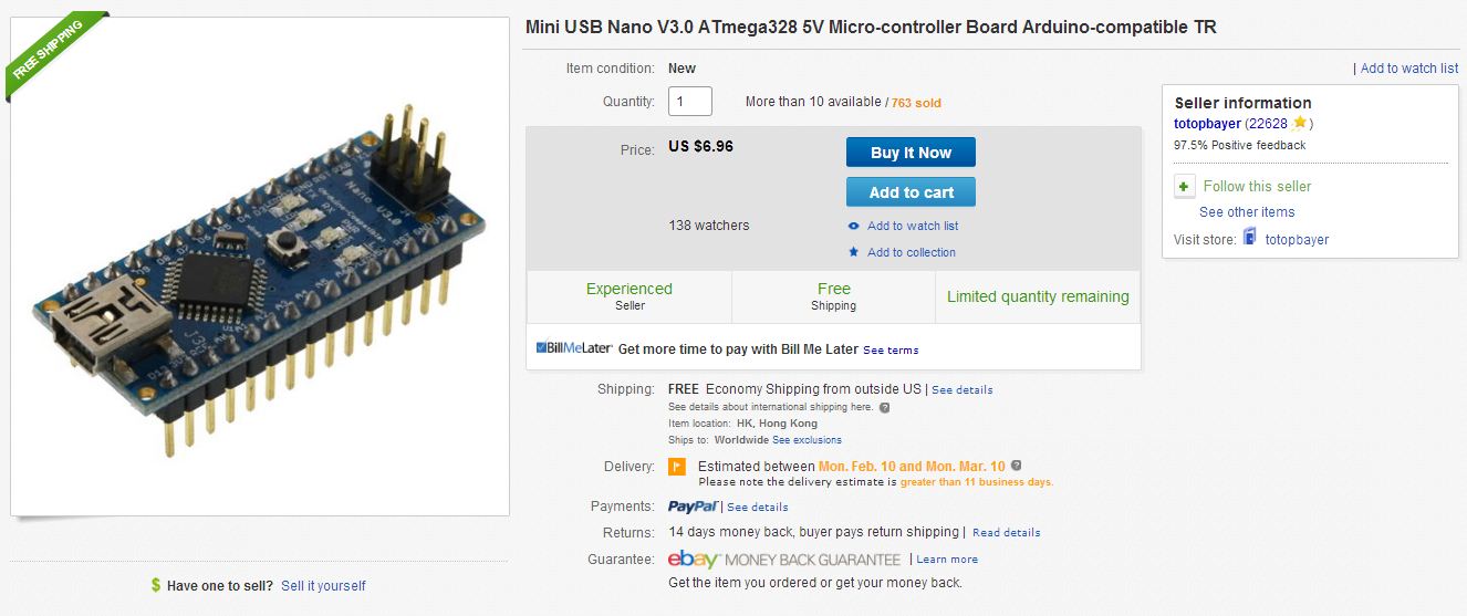
1. Microcontroller (Arduino Nano)- you will also need a mini usb cable to connect this device to your pc (not the same cable as all android phones currently- the older/fatter version):
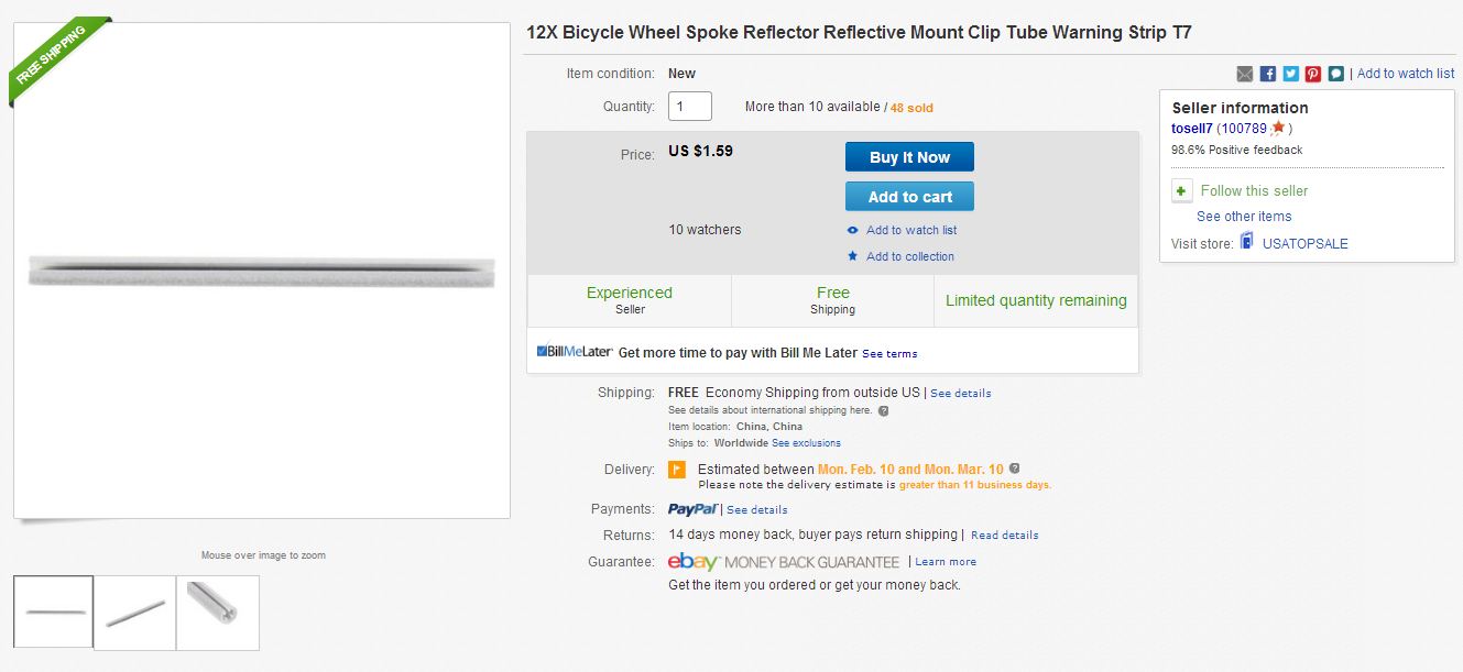
2. Bike spokes or tie rods:
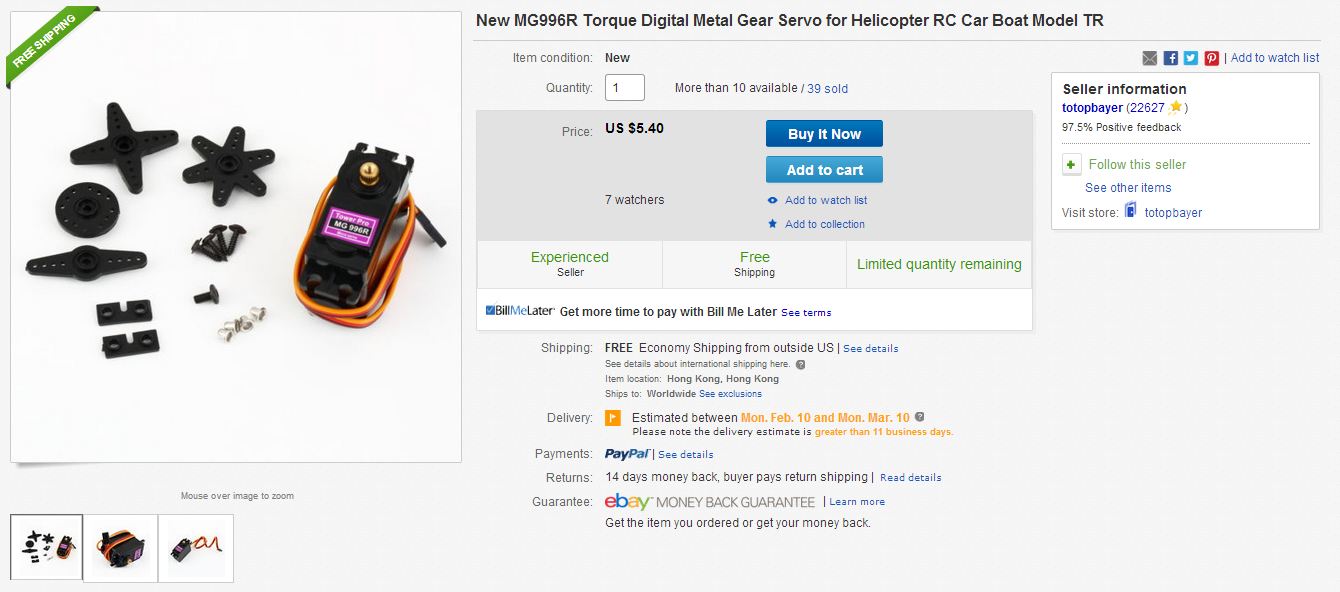
3. Servo with high torque (I originally used a 2-3kg/cm servo and ran into issues. Pay a dollar or two more and get something with 5+kg/cm of torque so you don't have to worry about the geometry of your bell crank etc.) This one pictured has 10kg/cm which was overkill:
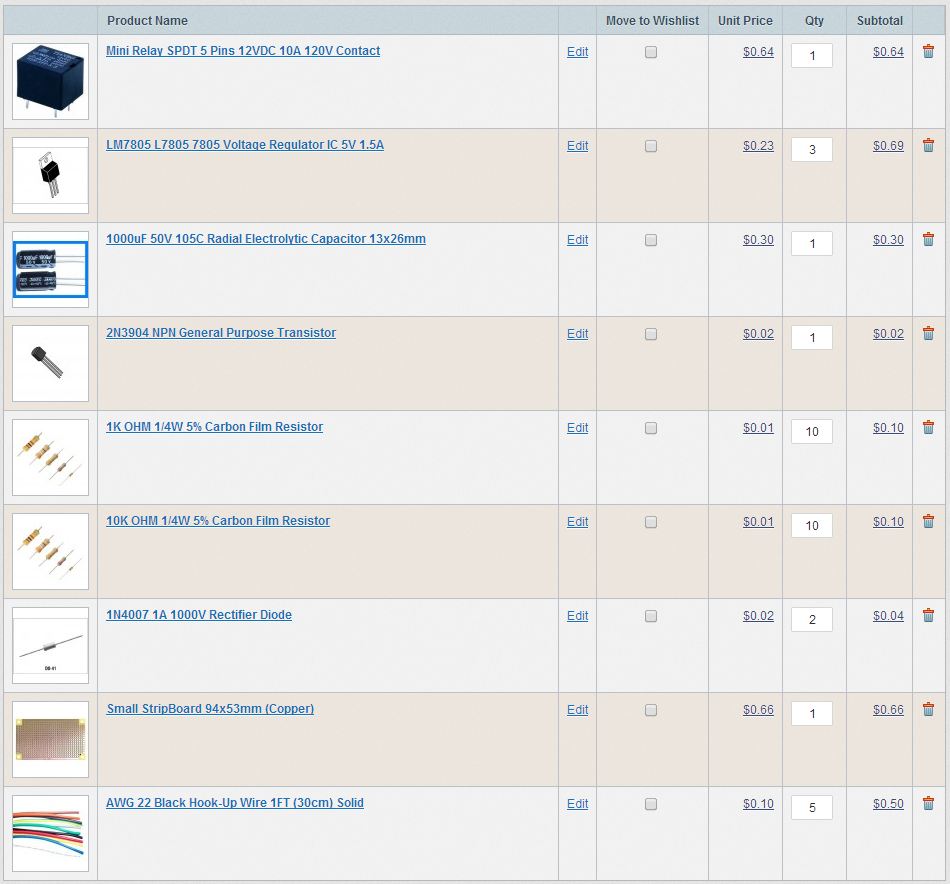
4. Actual component list according to schematic (ordered from http://www.taydaelectronics.com/ ):

5. Plexiglass and/or sheet metal to make the bell crank and push rod out of (get creative)
6. Screws to mount the servo to the plexiglass and the plexiglass to your waterfall (get creative).
Tools List:
1. Soldering iron and solder
2. Electrical tape
3. Pliers to bend spokes/tie rods
4. Dremel to cut plexi/sheet metal
5. Drill to drill holes into mechanical parts
6. PC for programming the microcontroller
Procedure:
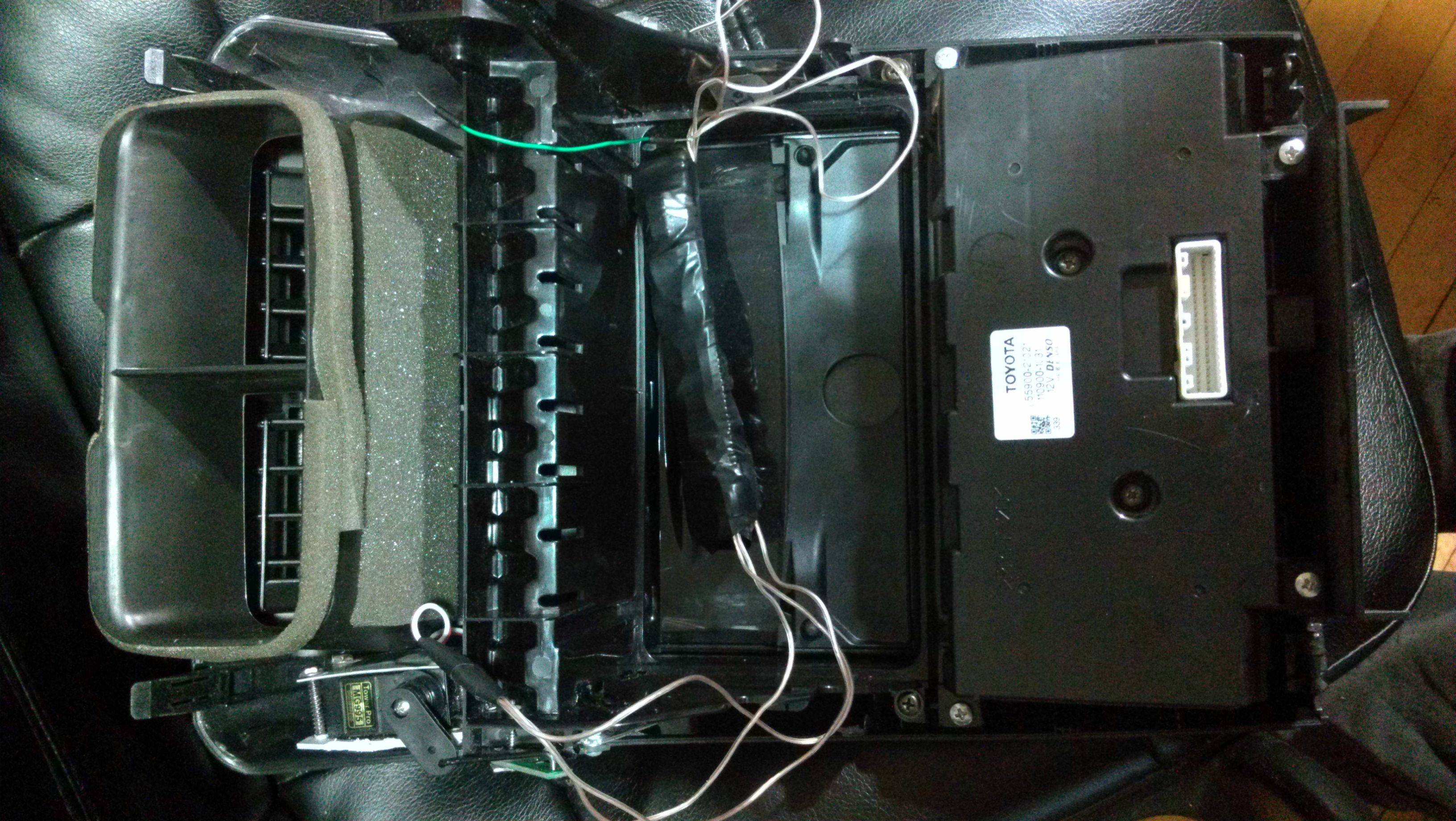
1. Cut an mount a piece of sheet metal or plexiglass to your waterfall to match the general outline of the grey piece in this picture:
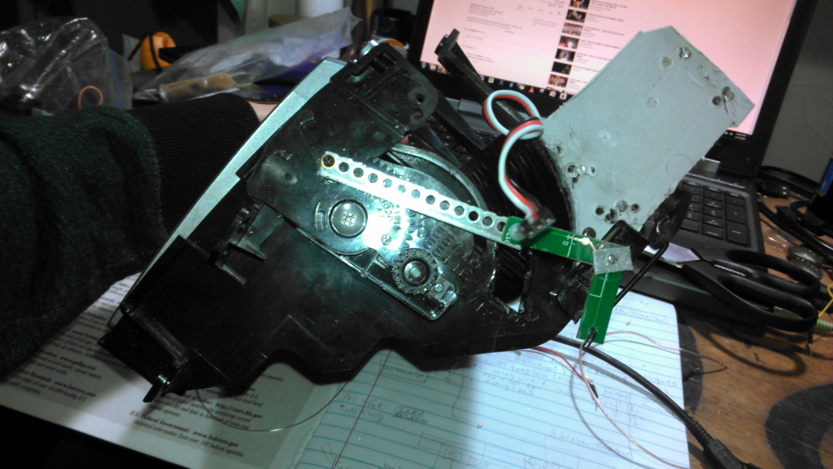
Screw it into your waterfall plastic using plastic screws.
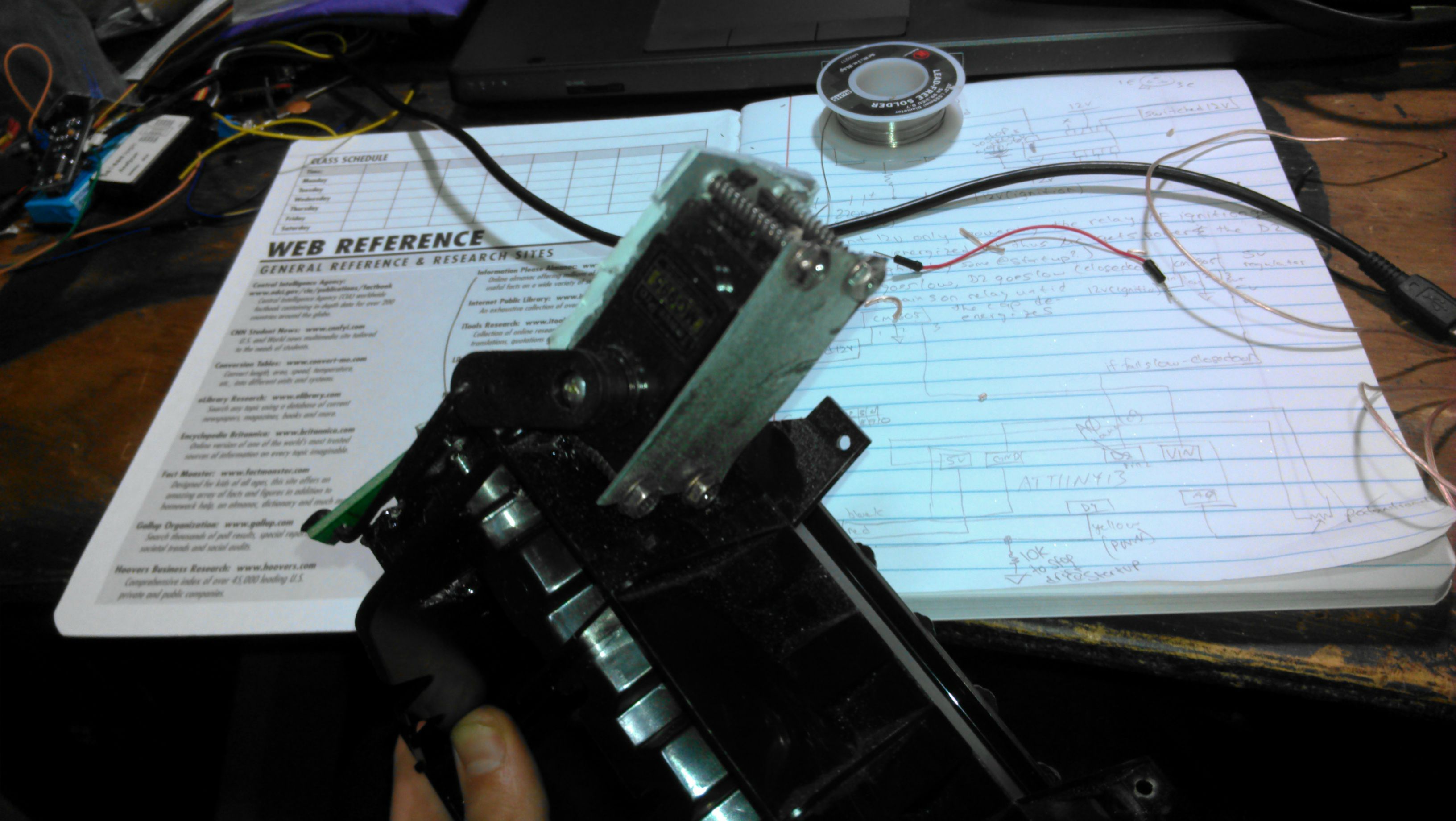
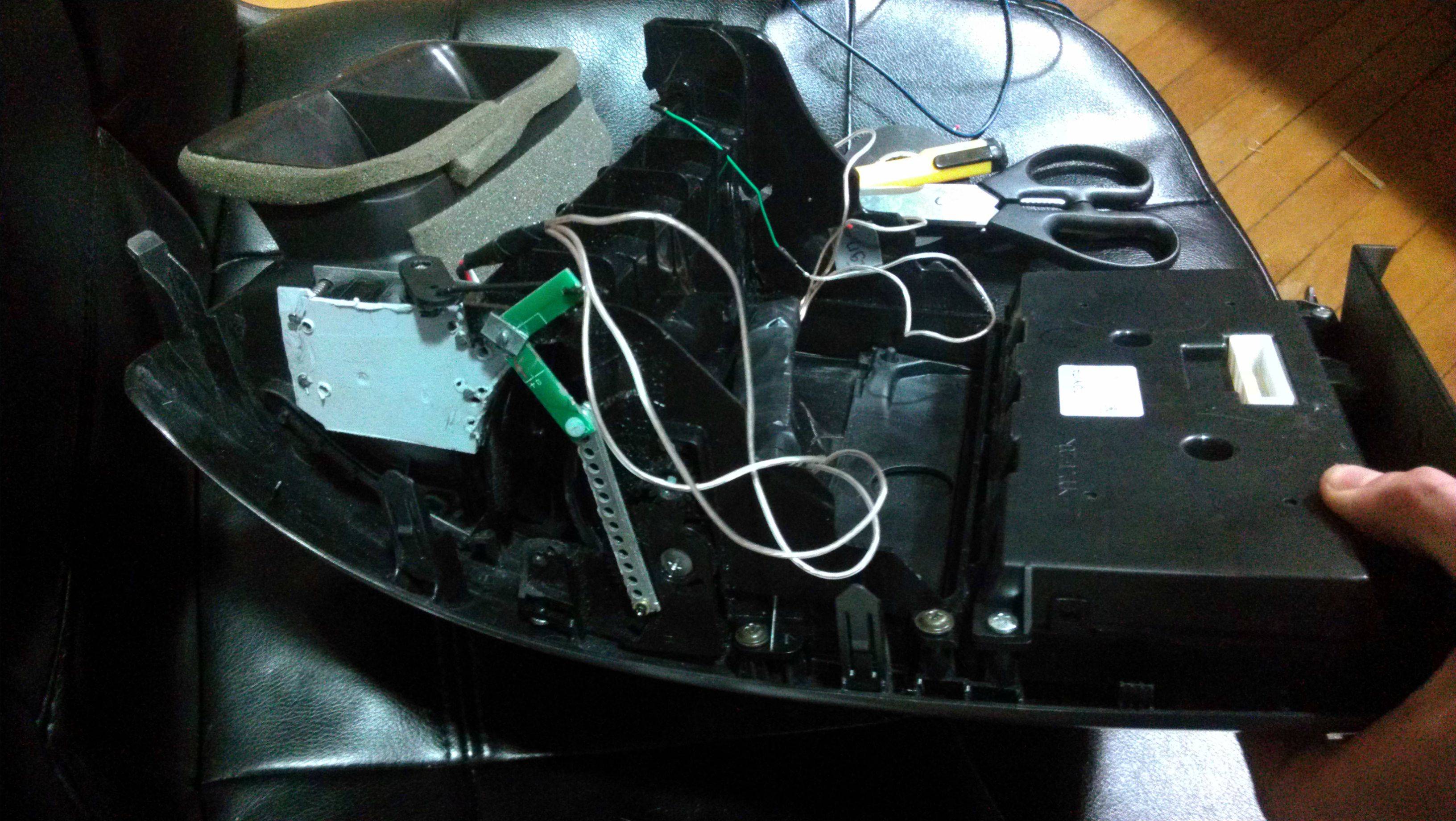
2. Make a back plate to mount your servo to that piece of plexiglass or sheet metal. Be sure that your servo is as close to the unit (towards my thumb in this picture):
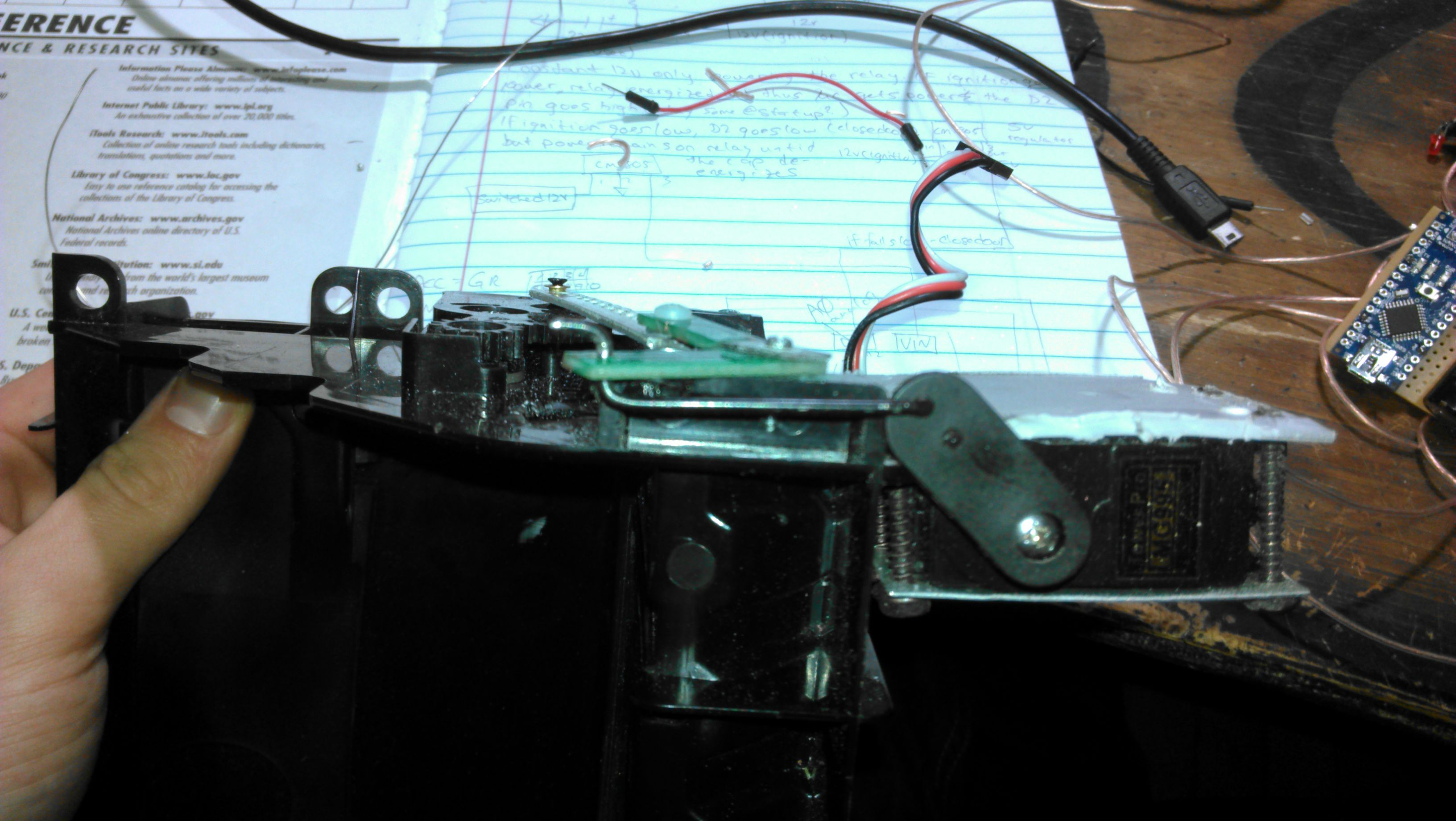
Another view:
3. Create a bell crank and push rod out of sheet metal or plexiglass and screw them in place:
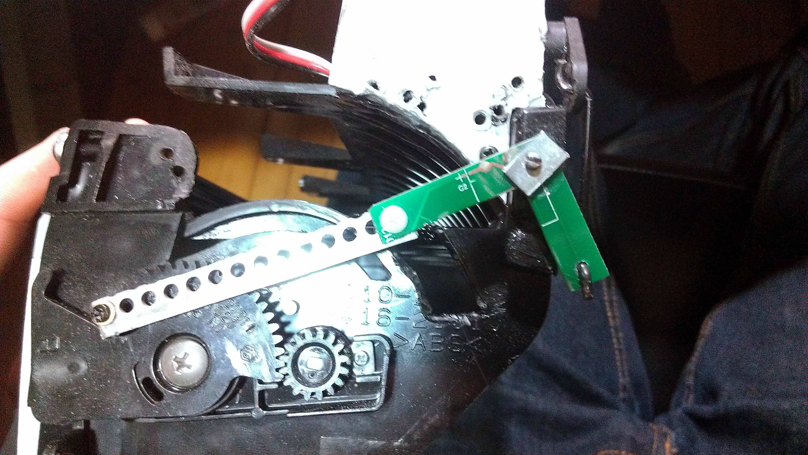
The far left screw is screwed into the little *** that hangs out. You have to drill a hole to screw there.
The middle bolt is a nylon bolt binding the push rod to the bell crank. It is no physically connected to the waterfall- it merely acts as a pivot point separate from the waterfall. I had to cut away some of my plastic to make room for the bolt underneath to slide freely.
The far right screw is a pivot point for the bell crank. Make sure that there is no tension on the bell crank when it swivels. The screw should be secure keeping the bell crank in place, but it should not rub or cause added resistance in the system.
4. Download and install the latest Arduino IDE. This is the program that allows you to program your microcontroller.
http://arduino.cc/en/Main/Software
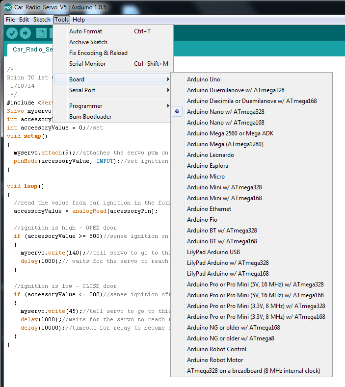
5. Create a new program in the Arduino IDE and select the Nano board:
6. Plug in your Arduino to your PC using the mini usb cable. Allow all auto updates. Select the correct serial port that it is connected to (typically the highest COM port in your list). If one doesn't compile then try another (or google how to determine which COM port your Arduino is connected to).
7. Upload your program to the device. Originally I used the following:

But I ran into issues if you tried to start the car multiple times in a minute or start it in really cold weather. Use this as sudo code if you would like to write it from scratch.
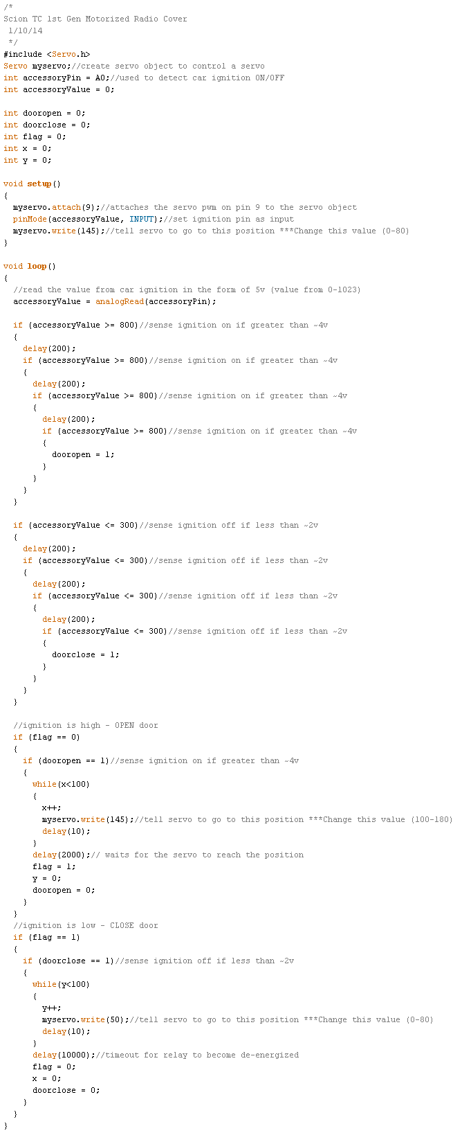
The final code that I used on my device is as follows:
Raw Text:
8. Paste the above code into the Arduino IDE and and press the upload button. If all went well, your code will have successfully uploaded onto your microcontroller:

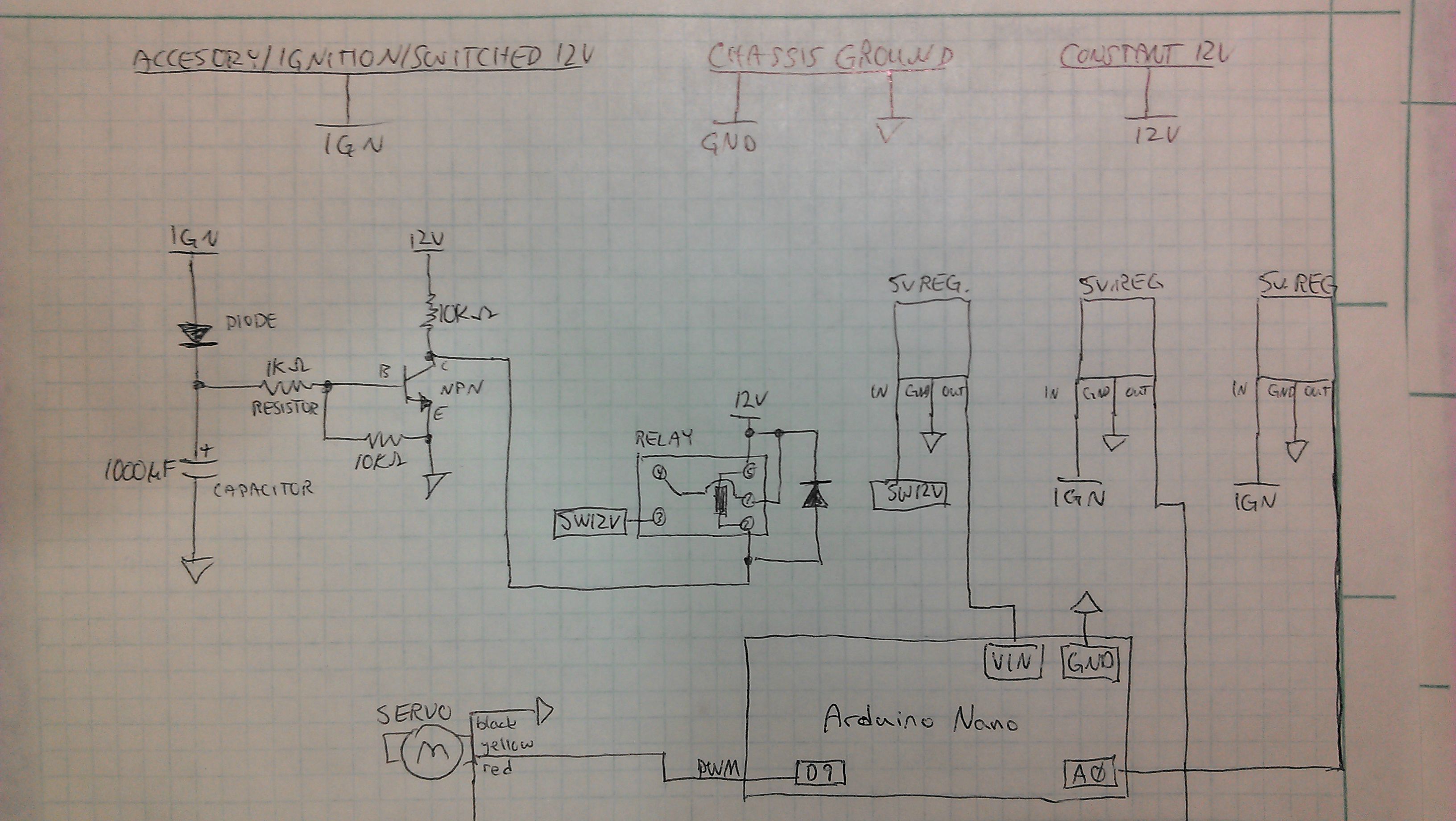
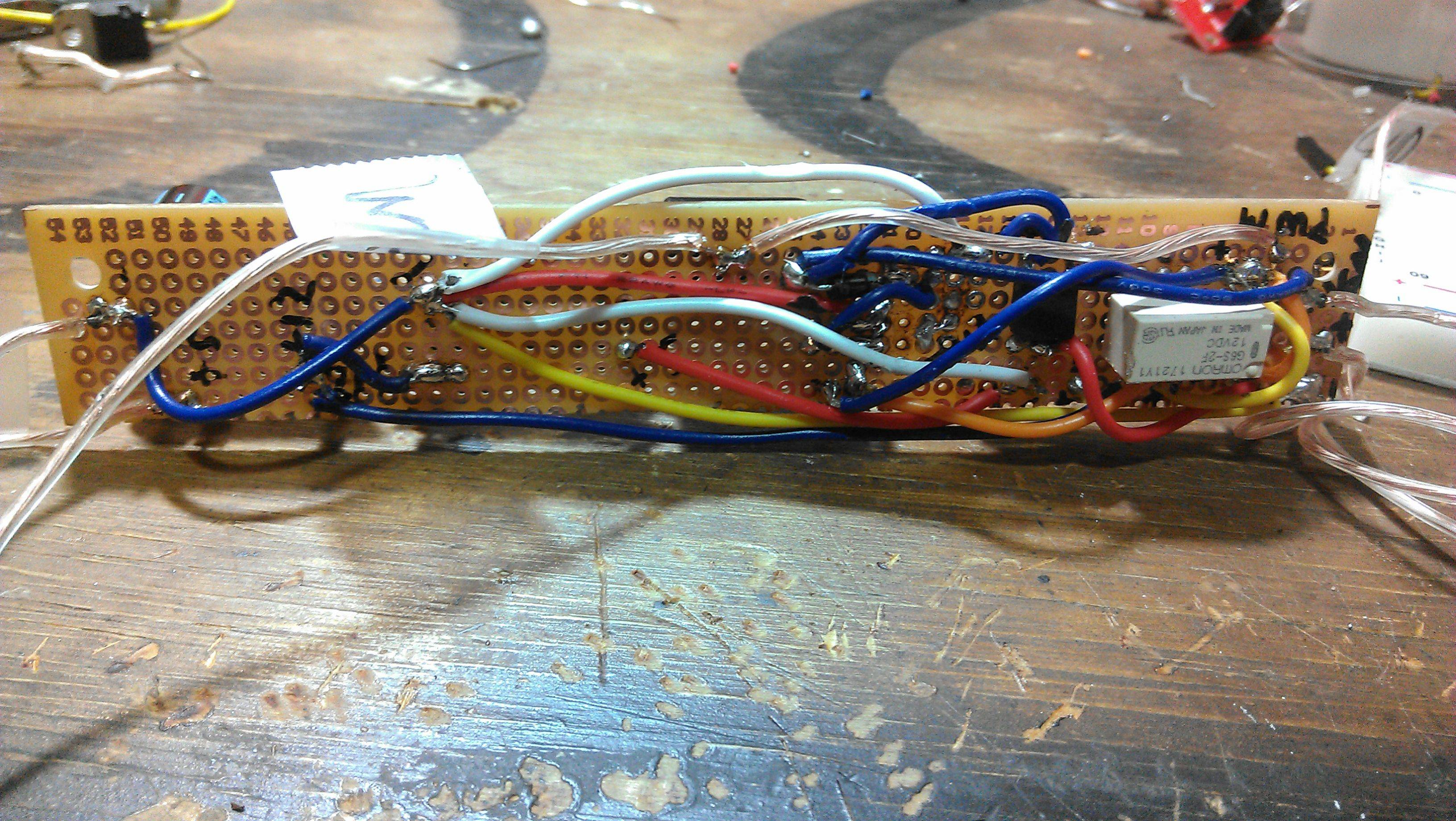
9. Create the schematic with the parts from the parts list according to the following:
I used a few car to USB regulators that I had laying around since I didn't have any 5v regulators:
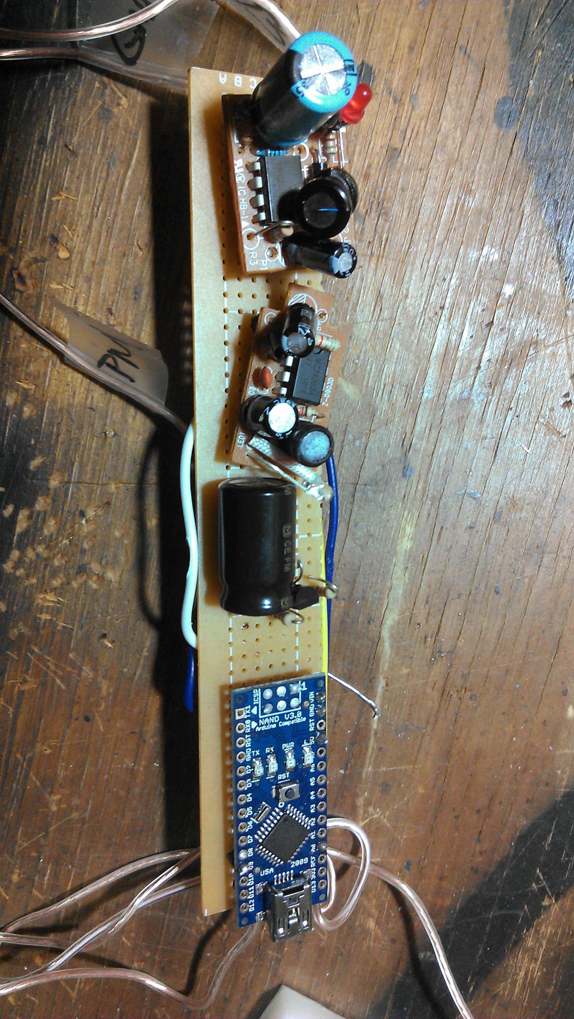
Bottom view:
Next wrap everything in electrical tape and leave a few feet of wire to go to your 12v, ground, and ignition:
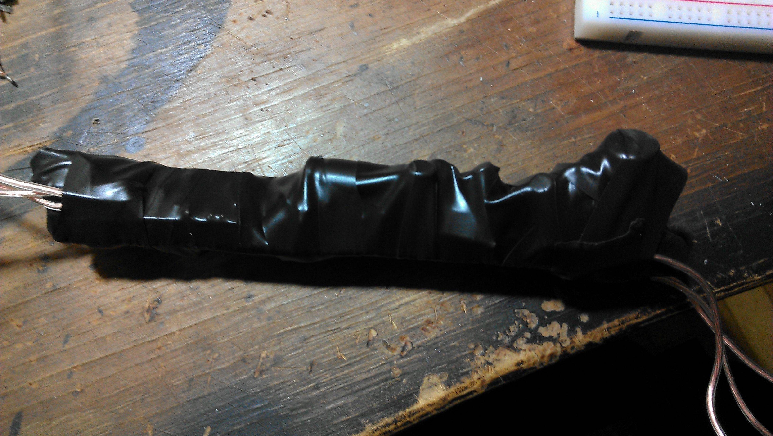
10. Slap it all together:
11. Mount it all back in your car. You'll have to look at other topics to determine where to tie into for 12v, ground and ignition- I'm sorry but I don't remember how I wired it.
The code is sloppy so if you would like to improve on it- please do and post your results. I have had the second version of code posted, working in my car now for 2 months with zero complaints.
If anyone else tried this, please post how you tied into 12v, ground, and ignition.
If you have any questions on removing the waterfall etc. please search the forum.
Anything that is unclear please say something and I will edit my original post- I am positive I left out a lot of crucial stuff.
Any other questions please just ask. I can't guarantee that I will answer instantly but I will try to check this topic every day for a few weeks to answer anything immediate. Thanks for the kind words and interest on my project guys!
https://www.scionlife.com/forums/sho...d.php?t=226418
I had enough interest in it so I decided to write up a short tutorial.
Honestly I wasn't expecting much interest and I'm new to the forum, so I didn't document anything very well- please bare with me.
I'll start with the final product. This is what you will end up with. When you start the car, the radio door opens. When you turn off your car, the radio door closes.
The device will not drain your battery as then entire circuit times out after ~10 seconds and all power going to the circuit cuts off until the next time you go to start your car.
Parts List:
I hate it when people post tutorials and they post links that are dead after a month. I uploaded pictures that I hope will last a bit longer than eBay listings etc. so that there's a better understanding of what you need. For this reason I have not posted direct links to each part and you will have to search for them yourself.
1. Microcontroller (Arduino Nano)- you will also need a mini usb cable to connect this device to your pc (not the same cable as all android phones currently- the older/fatter version):
2. Bike spokes or tie rods:
3. Servo with high torque (I originally used a 2-3kg/cm servo and ran into issues. Pay a dollar or two more and get something with 5+kg/cm of torque so you don't have to worry about the geometry of your bell crank etc.) This one pictured has 10kg/cm which was overkill:
4. Actual component list according to schematic (ordered from http://www.taydaelectronics.com/ ):
5. Plexiglass and/or sheet metal to make the bell crank and push rod out of (get creative)
6. Screws to mount the servo to the plexiglass and the plexiglass to your waterfall (get creative).
Tools List:
1. Soldering iron and solder
2. Electrical tape
3. Pliers to bend spokes/tie rods
4. Dremel to cut plexi/sheet metal
5. Drill to drill holes into mechanical parts
6. PC for programming the microcontroller
Procedure:
1. Cut an mount a piece of sheet metal or plexiglass to your waterfall to match the general outline of the grey piece in this picture:
Screw it into your waterfall plastic using plastic screws.
2. Make a back plate to mount your servo to that piece of plexiglass or sheet metal. Be sure that your servo is as close to the unit (towards my thumb in this picture):
Another view:
3. Create a bell crank and push rod out of sheet metal or plexiglass and screw them in place:
The far left screw is screwed into the little *** that hangs out. You have to drill a hole to screw there.
The middle bolt is a nylon bolt binding the push rod to the bell crank. It is no physically connected to the waterfall- it merely acts as a pivot point separate from the waterfall. I had to cut away some of my plastic to make room for the bolt underneath to slide freely.
The far right screw is a pivot point for the bell crank. Make sure that there is no tension on the bell crank when it swivels. The screw should be secure keeping the bell crank in place, but it should not rub or cause added resistance in the system.
4. Download and install the latest Arduino IDE. This is the program that allows you to program your microcontroller.
http://arduino.cc/en/Main/Software
5. Create a new program in the Arduino IDE and select the Nano board:
6. Plug in your Arduino to your PC using the mini usb cable. Allow all auto updates. Select the correct serial port that it is connected to (typically the highest COM port in your list). If one doesn't compile then try another (or google how to determine which COM port your Arduino is connected to).
7. Upload your program to the device. Originally I used the following:
But I ran into issues if you tried to start the car multiple times in a minute or start it in really cold weather. Use this as sudo code if you would like to write it from scratch.
The final code that I used on my device is as follows:
Raw Text:
Code:
/*
Scion TC 1st Gen Motorized Radio Cover
 1/10/14
 */
#include <Servo.h>
Servo myservo;//create servo object to control a servo
int accessoryPin = A0;//used to detect car ignition ON/OFF
int accessoryValue = 0;

int dooropen = 0;
int doorclose = 0;
int flag = 0;
int x = 0;
int y = 0;

void setup()
{
  myservo.attach(9);//attaches the servo pwm on pin 9 to the servo object
  pinMode(accessoryValue, INPUT);//set ignition pin as input
  myservo.write(145);//tell servo to go to this position ***Change this value (0-80)
}

void loop()
{
  //read the value from car ignition in the form of 5v (value from 0-1023)
  accessoryValue = analogRead(accessoryPin);

  if (accessoryValue >= 800)//sense ignition on if greater than ~4v
  {
    delay(200);
    if (accessoryValue >= 800)//sense ignition on if greater than ~4v
    {
      delay(200);
      if (accessoryValue >= 800)//sense ignition on if greater than ~4v
      {
        delay(200);
        if (accessoryValue >= 800)//sense ignition on if greater than ~4v
        {
          dooropen = 1;
        }
      }
    }
  }

  if (accessoryValue <= 300)//sense ignition off if less than ~2v
  {
    delay(200);
    if (accessoryValue <= 300)//sense ignition off if less than ~2v
    {
      delay(200);
      if (accessoryValue <= 300)//sense ignition off if less than ~2v
      {
        delay(200);
        if (accessoryValue <= 300)//sense ignition off if less than ~2v
        {
          doorclose = 1;
        }
      }
    }
  }

  //ignition is high - OPEN door
  if (flag == 0)
  {
    if (dooropen == 1)//sense ignition on if greater than ~4v
    {
      while(x<100)
      {
        x++;
        myservo.write(145);//tell servo to go to this position ***Change this value (100-180)
        delay(10);
      }
      delay(2000);// waits for the servo to reach the position
      flag = 1;
      y = 0;
      dooropen = 0;
    }
  }
  //ignition is low - CLOSE door
  if (flag == 1)
  {
    if (doorclose == 1)//sense ignition off if less than ~2v
    {
      while(y<100)
      {
        y++;
        myservo.write(50);//tell servo to go to this position ***Change this value (0-80)
        delay(10);
      }
      delay(10000);//timeout for relay to become de-energized
      flag = 0;
      x = 0;
      doorclose = 0;
    }
  }
}
9. Create the schematic with the parts from the parts list according to the following:
I used a few car to USB regulators that I had laying around since I didn't have any 5v regulators:
Bottom view:
Next wrap everything in electrical tape and leave a few feet of wire to go to your 12v, ground, and ignition:
10. Slap it all together:
11. Mount it all back in your car. You'll have to look at other topics to determine where to tie into for 12v, ground and ignition- I'm sorry but I don't remember how I wired it.
The code is sloppy so if you would like to improve on it- please do and post your results. I have had the second version of code posted, working in my car now for 2 months with zero complaints.
If anyone else tried this, please post how you tied into 12v, ground, and ignition.
If you have any questions on removing the waterfall etc. please search the forum.
Anything that is unclear please say something and I will edit my original post- I am positive I left out a lot of crucial stuff.
Any other questions please just ask. I can't guarantee that I will answer instantly but I will try to check this topic every day for a few weeks to answer anything immediate. Thanks for the kind words and interest on my project guys!

Thank you for taking the time to put this DIY together. I'm going to give this a try, but I'll have to read this over a few times and try to digest it all.
The mechanical/moving parts aspect I believe I can pull it off, but the circuit board side is a little confusing. My soldering and electrical experience only consisted of swapping LEDs out of my gauges/hvac.
Your sketch is somewhat helpful, but my lack of electrical experience still leaves me lost. I guess for now I'll start by gathering parts first and go from there.
Thread Starter
Senior Member
SL Member
Joined: Jul 2013
Posts: 100
No problem man. Like I said, I'm here to help you with any issues you might face- worst comes to worst I'll just make the circuit for you and ship it to you. I already have all the parts laying around anyways.

Thread
Thread Starter
Forum
Replies
Last Post
airmankevin1
Scion tC 1G Owners Lounge
26
Feb 14, 2018 01:23 PM