
cathode wiring diagram needed help..please


Thread Starter
Senior Member
SL Member
Joined: Sep 2007
Posts: 245
From: Miami, Fl
well i got my ozniums cold cathode kit already, and was wondering if any of you have any diagrams i could go by to achieve what i want to to, here is what i basically how i want my set up to operate:
I want it to operate using a switch. I want them to come on when my door opens or when I unlock the car, tapped into the dome lights to activate when the doors open and unlock, and also with the switch added so I can take control once my doors close. I plan on also doing the cup holders with 5mm pre-wired leds. I would prefer to have them running off the same power source and switch.
Here is a list of all the items I have for the install:
(2) 12� cold cathodes.
(1) Dual output transformer.
(1) Scion OEM style rocker switch.
(2) 10 amp ATC fuses.
(1) ATC fuse holder � (16 gauge).
20ft. of red hook up wire � (18 gauge).
Add � a � circuit for mini type fuses

Thread Starter
Senior Member
SL Member
Joined: Sep 2007
Posts: 245
From: Miami, Fl
tell me about it..there was another member "scionjim" who kindly offered to draw me up a diagram, this is the same way his is set up, but has not gotten back to me, and its been a while now, so i guess he decided not to do it for me

hey man. yes i said i would write up a DIY for you. I have been extremely busy at my job. I work in radio doing IT and other stuff on radio and we have had huge issues. I was sent to california and Chicago to fix stuff. Its been a mess. I barely had time to even turn on my PC and when I did I had to VPN into work and fix servers and other crap. Its been a mess and i feel like im dying. Anyways, this is my first time back on here in a while and i noticed another post that wants to do exactly what you want. Hopefully you understand it. You basically need a relay if your going to do it the way you want. Just read this post. You should catch the drift of it. Sorry about not making the DIY for you yet, I usually follow through and write up DIYs for people that ask. Im never like this. Its just been busy as hell for me and it was all unexpected. Sorry man. Let me know if you understand what they mean on this other post. If not, post up any questions on you post. It looks like i will be able to get on here all day. Good luck.
And just to let you know, if you want to do it an easier way which would need no relay, then i would buy a 3 way ON OFF ON switch. This would be my preference.
https://www.scionlife.com/forums/viewtopic.php?t=195923
And just to let you know, if you want to do it an easier way which would need no relay, then i would buy a 3 way ON OFF ON switch. This would be my preference.
https://www.scionlife.com/forums/viewtopic.php?t=195923
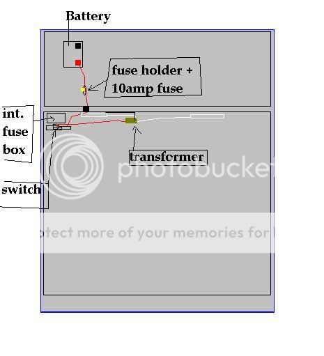
Hey man, Well I drew up a quick DIY for you using a 3 way ON OFF ON switch for you. I would recommend doing it this way with this stlye switch. Otherwise you need to use a relay and wire it up and if your not comfortable wiring, then the relay way isnt for you like in my previous LINKED post. Anyways, i would do it like this and just buy a ON OFF ON switch. You can return that OEM switch to oznium and get a 3 way which i would recommend. Here ya go. The 2nd pic os for reference of the power and ground locations. Sorry that this PAINT pic looks blurry. It got resized on the website here. Anyways, it seems like you can read it all though except the blue things....which are your Cathodes. Don not pay attention to the rocker swithc words that are written on the second pic for the 12volt power. I used this pic for another persons DIY. So pay not attention the the rocker switch ON OFF text. Here ya go man.


im not sure what the add a circuit is. i think its the same as the fuse holder which you have and need for safety. http://www.oznium.com/atc-fuse-holder. If its the same thing, then you need it. If its not the same, then alls you need is the ATC fuse holder which you have and is the BLACK FUSE i did in the PAINT pic.
Thread Starter
Senior Member
SL Member
Joined: Sep 2007
Posts: 245
From: Miami, Fl
i just placed my order for the switch, and have printed out the diagram, as for the add-a-circuit this is what it looks like
Add-A-Circuit Fuseholder For Mini Fuses
This ingenious device allows quick and easy installation of additional accessories without the need for splicing. For use with Mini Knife fuses. Includes installation instructions. Max rating: 10 amps.

the only reason i bought it, was because it was recomended by phil from ozniums, and is also in his write up here
http://www.oznium.com/forum/topic11824
Add-A-Circuit Fuseholder For Mini Fuses
This ingenious device allows quick and easy installation of additional accessories without the need for splicing. For use with Mini Knife fuses. Includes installation instructions. Max rating: 10 amps.
the only reason i bought it, was because it was recomended by phil from ozniums, and is also in his write up here
http://www.oznium.com/forum/topic11824
Thread Starter
Senior Member
SL Member
Joined: Sep 2007
Posts: 245
From: Miami, Fl
one more thing will it be easy to wire up this set also to illuminate my cupholders, which i bought 5mm Super bright pre-wired LED lights
http://www.oznium.com/prewired-leds
http://www.oznium.com/prewired-leds

Senior Member
SL Member
Joined: Jun 2006
Posts: 375
hey...great diagram....only one problem with it, you have to make sure the fuse comes after the constant power source....so BATTERY>FUSE>(through the firewall)>SWITCH>CATHODE TRANSFORMER
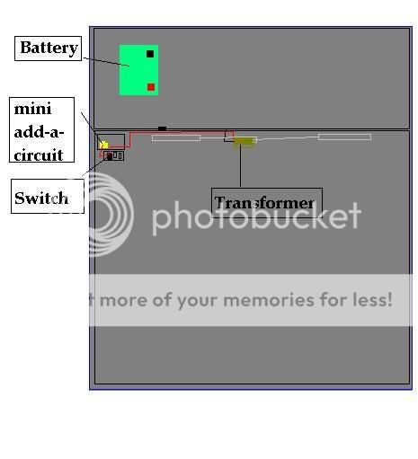
the mini add-a-circuit is a simple way of tapping directly into the interior fusebox and therefore running power from inside and already having it with a fuse....if you are wiring in through the batery and already have a fuse holder with a fuse, the add-a-circuit is useless to you....if you are wiring in from the inside fusebox then you only need to plug in the mini add-a-circuit in the fusebox and from there go straight to the switch
The mini add a circuit is the simplest and fastest of all methods because you dont have to go through the firewall and its already fused and its extremely close to the switch....good luck =D
allow me to illustrate
Going through battery and firewall (PITA if its your first time finding the firewall)
Mini add-a-circuit method (easiest and fastest)
OK well now i see. They can do the same thing as the add a fuse if wired correctly. I would still keep the add a fuse and wire it like in my paint pic. If you use the add a circuit, it just eliminates the need of the 12volt power source. You would get power from the add a circuit and not have to wire it to the 12volt power source. The only issue with using this is having to find a circuit in your fuse box that has constant power to it. I would wire it the way i have it and save yourself the time of using a multimeter to try and find the right circuit spot in your fuse box because it can be difficult. Either way will work. Your choice, i would stick with the way in my paint diagram because its easier and you dont need to search for power in the fuse box. Just use the power source in the pic i gave you. Your choice. O an here the pic of the dome light wire...Its the blue negative wire that you need to tapinto using a negative wire only.

O and ESISSO, My diagram is 100% correct. This is the method i use in my car and its worked for 2 years. Plus im not getting power straight from the battery. Its coming for the incar terminal located near the fuses. And if you looked at the diagram correctly, the fuse does come after the power source. So stc08, dont worry, my diagram is correct.
Thread Starter
Senior Member
SL Member
Joined: Sep 2007
Posts: 245
From: Miami, Fl
Scionjim, i am going with your diagram for my install, what extra steps do i need to take to also include the 5mm pr-wired leds for my cup holders..and just curious someone before had told me that for the lights to work on a switch and on the domelight i would need to wire in a diode # 1N4001 from radio shack..whats that all about..man i guess theres so many ways to do this, but im sticking with yours seems the easiest
are you talking about resistors for the LEDs? If they are not prewired with them, then you will need to add them in. Let me know and ill tell you about it?
Its these: http://www.radioshack.com/product/in...entPage=search
But if you purchased these from OZNIUM, then there is no need for the diodes and you'll be okay because OZNIUM pre-installs resistors (diodes) under the heat shield on these LEDs.
http://www.oznium.com/prewired-leds
So let me know, but i think your already OK to go if you purchased from oznium.
Alright then. You'll be fine and don't need anything else. Just hook them up. I've updated the diagram to include the LEDs off the same switch and to turn on and off just like the cathode will. The blue circles are the LEDs. Black wire is negative and red is positive like always. Here ya go:

alright, sounds good man. I'll be on and off the site today and tomorrow, so if you run into issues, post it up and let me know and i'll help out the best i can. Again, sorry for the long delay of my response. Its been crazy with work. Im usually not like this and am on top of things ASAP. Its just been crazy. Anyways, looks like your all set now. Keep us updated. Good luck.