
DIY: LED DRL's

Thread Starter
Senior Member
SL Member
Joined: Jun 2011
Posts: 752
From: Houston, TX
I know what most of you who saw this are thinking, and no, I did not open my headlight housing of the brand new car, that I haven�t even made a payment on yet!
I got some LED strips and mounted them at the top of my headlight housing. I am using them as DRL�s, but I also installed a switch because the current LED strips are �good old Wally world specials,� and I do not trust them running 24/7. I went ahead with the install though, because now the wiring is all there for an upgrade later.
I am sure a lot of you on this website are old pros at jobs like this, but for me, this was a bit of a PITA, which is why I figured I would do a DIY and help some other rookies out. But please note:
I am in no way responsible if you shock yourself, or start an electrical fire, resulting in the loss of your vehicle while following this guide. I am not a professional; I figured this out by trial and error. I do not know the long term effects of using these products on your vehicle. Use at YOUR OWN RISK!!!!!!!
Supplies:
20-30 feet 16 gauge wire: $6 (you could use a lower gauge/bigger wire if you choose, but not needed)
Mini Add-a-Circuit plug: $7 found in the electrical section of most auto parts stores
16 gauge environmental splices 5-10: $5 for a pack of 10 (the kind you melt the outer plastic to seal the connection and keep water out
Wire strippers & Crimpers: $10 for a cheap pair, but that will be fine for this
Switch $6 this is completely optional and prices vary, I got a switch that lights up : ) that�s why it was $6
Female splice connectors: $4 pack of 10 (optional, only needed if you install a switch)
Post terminals: $4 pack of 10
8-12 inch LED flexible light strips: $18 at W.M. but you can use any as long as they are waterproof
Before we begin I would like to explain why I used the interior fuse box. MightyP who is also a Scionlife member is very knowledgeable and had already searched all over the engine bay looking for a place to tap power from that was only getting current when the ignition was on. He found the MAF sensor, but that was about it. Call me crazy, but I haven�t even made a payment yet, the last thing I wanted to do was be cutting any wires on my new car. All of the fuses under the hood are constantly hot (always have power) so if I did it there, I would need a switch to turn them off, which meant running wires to the cab anyway, so why not start there?
First remove the cabin fuse box cover, located under, and right of the steering wheel in the cab. I used the WASHER FF fuse space which has a 10 Amp fuse. If this is the fuse you want to use, then go ahead and pull it out. There is a fuse puller in the car, in the main fuse box under the hood. This only has power when the ignition is on. PIC

Now, on your add-a-circuit, there are 2 holes to add fuses. The weird stock fuse will not work in the add-a-circuit so you will need to use the 10 amp that comes in the box in the first hole, closest to the metal arms of the add-a-circuit. PIC

Then put in the 3 amp fuse that comes in the add-a-circuit box into the 2nd hole, the hole in line with the wire. Put this to the side for now. PIC

Next, cut a 15-20 inch piece of wire from the spool of 16 gauge wire. Strip both ends � of an inch. Add a Female splice connector to one end, and a Post terminal to the other. This wire will be our ground for our switch. PIC

Hook the post terminal end to the bolt labeled E (for earth ground) that is located in the drivers� left side kick panel. This panel is easily removed by popping out the driver�s door skip plate, and then the kick panel will come out with gentle persuasion. PIC

Next slide the Female splice connector side to your switch, the post labeled ground. Lay this down on the floor and pop your hood, time to put in the lights.
The LED�s I used were 12 inches, and you can cut them. 12 inches is a little long, so I cut off the last 3 on each strip. Clean the top of the headlight housing so that the 3M tape holds good. Center the lights the best you can and mark if you need too. I eye ball�ed it. PIC

Use the existing wire that you haven�t cut off yet on the strips, (EDIT: My lights were very cheap, and had cheap 20 gauge wires. I cut that all off except about 6 inches at each light.) and add a splice to each wire. Read your LED packaging so that you know which wire is + and which it ground. Ensure you cut enough of the 16 gauge wire to run the Positive + to the cabin. I ran mine down the driver�s side, under the hood channel. This wire I ran to the driver�s side light, then ran the passenger side positive wire to the drivers, and spliced them together, that way I didn�t have 2 separate wires running to the cabin. You can hide the wire from the passenger side under the radiator cover. PIC

I ran the ground wires to a good ground bolt labeled E next to the battery. (Used 2 ground wires because I goofed and had already hooked up the drivers side) PIC

Once you get this situated, go back to the driver�s seat. Connect a female splice connector to the positive wire that you ran from the lights, then slide that onto your switch labeled to accessory, or power out, however your switch is labeled.
Now, take your add-a-circuit and crimp a 15-20 inch piece of 16 gauge wire to it, then on the other end of the wire, add a female splice connector. Slide the connector onto your switch labeled DC in/power in. Plug the add-a-circuit into the empty fuse hole (the one you removed) with the wire coming out the side facing AWAY from you, toward the engine bay/firewall. (This is important because if you do it the other way, the 3amp fuse is now hooked to your washer fluid spray motor, and it will blow the first time you use it!) PIC

Turn your car on and flip the switch to test! Now go back and figure out where you will mount your switch and you are done. I used a dremal tool and about 45 minutes of time to reuse one of the factory dead switches for my switch to mount. PIC


This is the way I did it. Im sure there are other/better/worse ways of wiring these in. This is to help guide to get you headed in the right direction. If anyone has any better ideas, PLEASE share! Thanks!
I got some LED strips and mounted them at the top of my headlight housing. I am using them as DRL�s, but I also installed a switch because the current LED strips are �good old Wally world specials,� and I do not trust them running 24/7. I went ahead with the install though, because now the wiring is all there for an upgrade later.
I am sure a lot of you on this website are old pros at jobs like this, but for me, this was a bit of a PITA, which is why I figured I would do a DIY and help some other rookies out. But please note:
I am in no way responsible if you shock yourself, or start an electrical fire, resulting in the loss of your vehicle while following this guide. I am not a professional; I figured this out by trial and error. I do not know the long term effects of using these products on your vehicle. Use at YOUR OWN RISK!!!!!!!
Supplies:
20-30 feet 16 gauge wire: $6 (you could use a lower gauge/bigger wire if you choose, but not needed)
Mini Add-a-Circuit plug: $7 found in the electrical section of most auto parts stores
16 gauge environmental splices 5-10: $5 for a pack of 10 (the kind you melt the outer plastic to seal the connection and keep water out
Wire strippers & Crimpers: $10 for a cheap pair, but that will be fine for this
Switch $6 this is completely optional and prices vary, I got a switch that lights up : ) that�s why it was $6
Female splice connectors: $4 pack of 10 (optional, only needed if you install a switch)
Post terminals: $4 pack of 10
8-12 inch LED flexible light strips: $18 at W.M. but you can use any as long as they are waterproof
Before we begin I would like to explain why I used the interior fuse box. MightyP who is also a Scionlife member is very knowledgeable and had already searched all over the engine bay looking for a place to tap power from that was only getting current when the ignition was on. He found the MAF sensor, but that was about it. Call me crazy, but I haven�t even made a payment yet, the last thing I wanted to do was be cutting any wires on my new car. All of the fuses under the hood are constantly hot (always have power) so if I did it there, I would need a switch to turn them off, which meant running wires to the cab anyway, so why not start there?
First remove the cabin fuse box cover, located under, and right of the steering wheel in the cab. I used the WASHER FF fuse space which has a 10 Amp fuse. If this is the fuse you want to use, then go ahead and pull it out. There is a fuse puller in the car, in the main fuse box under the hood. This only has power when the ignition is on. PIC
Now, on your add-a-circuit, there are 2 holes to add fuses. The weird stock fuse will not work in the add-a-circuit so you will need to use the 10 amp that comes in the box in the first hole, closest to the metal arms of the add-a-circuit. PIC
Then put in the 3 amp fuse that comes in the add-a-circuit box into the 2nd hole, the hole in line with the wire. Put this to the side for now. PIC
Next, cut a 15-20 inch piece of wire from the spool of 16 gauge wire. Strip both ends � of an inch. Add a Female splice connector to one end, and a Post terminal to the other. This wire will be our ground for our switch. PIC
Hook the post terminal end to the bolt labeled E (for earth ground) that is located in the drivers� left side kick panel. This panel is easily removed by popping out the driver�s door skip plate, and then the kick panel will come out with gentle persuasion. PIC
Next slide the Female splice connector side to your switch, the post labeled ground. Lay this down on the floor and pop your hood, time to put in the lights.
The LED�s I used were 12 inches, and you can cut them. 12 inches is a little long, so I cut off the last 3 on each strip. Clean the top of the headlight housing so that the 3M tape holds good. Center the lights the best you can and mark if you need too. I eye ball�ed it. PIC
Use the existing wire that you haven�t cut off yet on the strips, (EDIT: My lights were very cheap, and had cheap 20 gauge wires. I cut that all off except about 6 inches at each light.) and add a splice to each wire. Read your LED packaging so that you know which wire is + and which it ground. Ensure you cut enough of the 16 gauge wire to run the Positive + to the cabin. I ran mine down the driver�s side, under the hood channel. This wire I ran to the driver�s side light, then ran the passenger side positive wire to the drivers, and spliced them together, that way I didn�t have 2 separate wires running to the cabin. You can hide the wire from the passenger side under the radiator cover. PIC
I ran the ground wires to a good ground bolt labeled E next to the battery. (Used 2 ground wires because I goofed and had already hooked up the drivers side) PIC
Once you get this situated, go back to the driver�s seat. Connect a female splice connector to the positive wire that you ran from the lights, then slide that onto your switch labeled to accessory, or power out, however your switch is labeled.
Now, take your add-a-circuit and crimp a 15-20 inch piece of 16 gauge wire to it, then on the other end of the wire, add a female splice connector. Slide the connector onto your switch labeled DC in/power in. Plug the add-a-circuit into the empty fuse hole (the one you removed) with the wire coming out the side facing AWAY from you, toward the engine bay/firewall. (This is important because if you do it the other way, the 3amp fuse is now hooked to your washer fluid spray motor, and it will blow the first time you use it!) PIC
Turn your car on and flip the switch to test! Now go back and figure out where you will mount your switch and you are done. I used a dremal tool and about 45 minutes of time to reuse one of the factory dead switches for my switch to mount. PIC
This is the way I did it. Im sure there are other/better/worse ways of wiring these in. This is to help guide to get you headed in the right direction. If anyone has any better ideas, PLEASE share! Thanks!
Last edited by KidJustin; Oct 15, 2013 at 02:28 AM. Reason: spelling


Thread Starter
Senior Member
SL Member
Joined: Jun 2011
Posts: 752
From: Houston, TX
@ tugatito12: I have more pics on my profile, but I will get some more in this thread when I get off work later.
@ everyone eles: thanks for the encouragement! Took me almost as long to write the DIY as it did to actually install.....
@ everyone eles: thanks for the encouragement! Took me almost as long to write the DIY as it did to actually install.....


Thread Starter
Senior Member
SL Member
Joined: Jun 2011
Posts: 752
From: Houston, TX
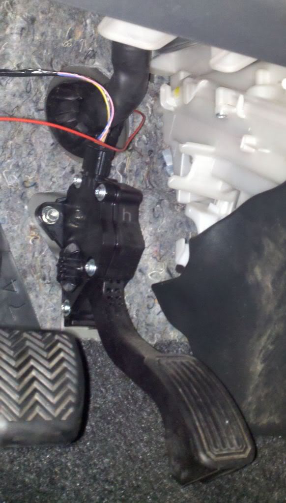
I dident go throught the fire wall. I routed the wire on the drivers side door, under the seal. The seal holds it well enough that it doesent move. I was actually hoping someone would come up with a good spot to go through the firewall, as the way I have it is a little ghetto
Firewall is a PITA to get through on the drive side. Just not much room to work with. Passenger side has a lot more room in the engine bay to work with if you're okay going the long way around.
When I redo my DRLs, I'm planning on going through the firewall, into the cabin. I'll take pictures of how I do it. Right now, the plan is to run a separate wire from the cabin to the engine bay, then splice the LEDs to the wire.


Senior Member
SL Member
Joined: Jan 2011
Posts: 388
From: St. Louis, MO
Great job bro!!! I actually just tapped into the corner lights wires. Good thing about LED it uses very little power. You just use '3M quick connects' (no cutting or splicing) for the connections. LED positive goes to corner lights positive and LED negative goes to corner lights negative. The LED strips will be on when you turn on parking/corners lights and stays on when headlights are on.
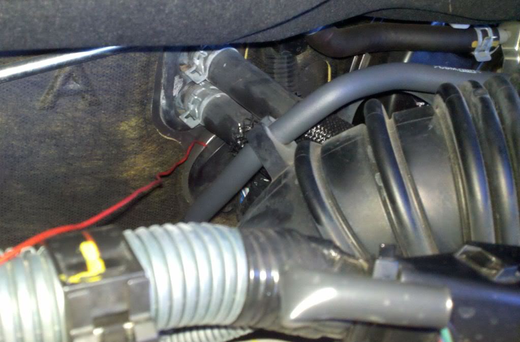
Here is where I went through the firewall. It was easier than I thought it would be and only took about 10 min to shove the right length of wire through and put the rubber grommet back in place.
The pictures show the wire in the open so you can see where I went through the firewall. I will hide the wire when I get the new LEDs in from Oznium.
The pictures show the wire in the open so you can see where I went through the firewall. I will hide the wire when I get the new LEDs in from Oznium.
Thread Starter
Senior Member
SL Member
Joined: Jun 2011
Posts: 752
From: Houston, TX
Yet anouther idea stolen from MightyP!

Senior Member
SL Member
Joined: Apr 2011
Posts: 135
From: New Orleans
Hmmm i already did it. they look nice. I did the door thing, but i can always go back and reroute it. I'll look tomorrow and see where that spot mightyp is talking about. is it easy to get to? do i need to take off anything? or can i just shove that peice over thats covering the hole?
I didn't actually go through the rubber stopper, I went next to it. And, no, it's not hard to get to. My short butt was able to push the wire through, next to the rubber grommet without moving anything. Just push the grommet out of the hole a little, then push a bit of wire through. Go to the cabin and PULL! 