
DIY LED Foot well Lights


Thread Starter
Senior Member

SL Member
Joined: Nov 2011
Posts: 292
From: New York
This is definitely one of the easier mods you can do to your car. To do this you need some kind of L.E.D. light bars, I used the starter kit from ledunderbody.com, an add-a-circuit, an extra 10amp fuse and 2 electrical connectors.
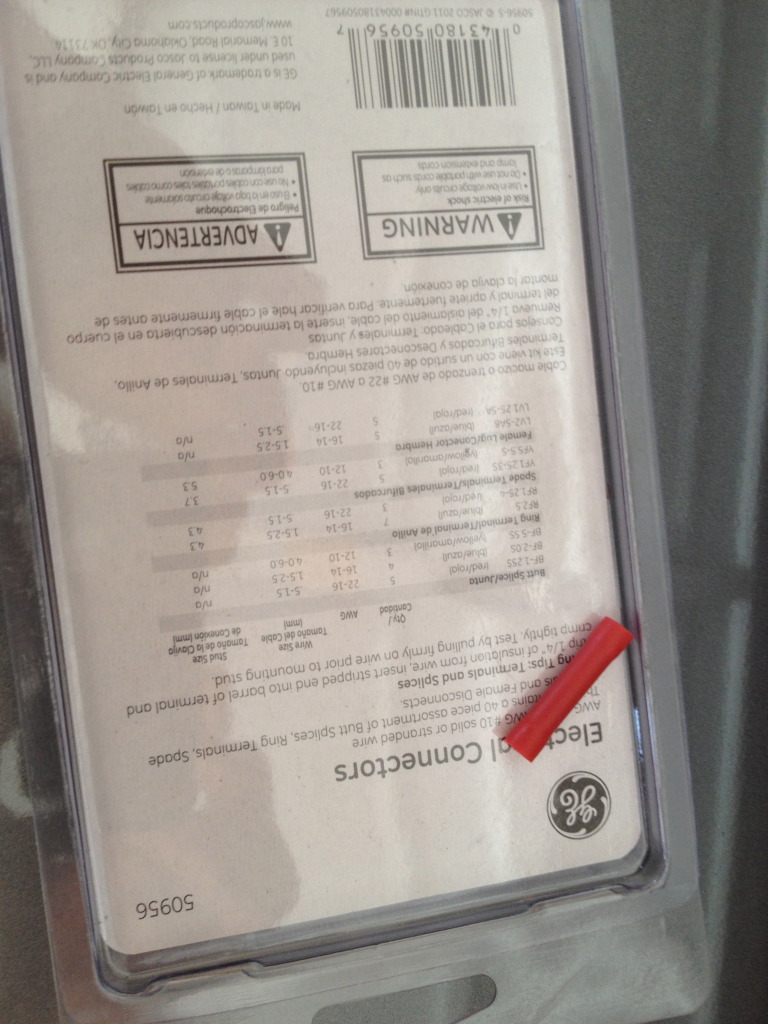
You're gonna need two of these. (These are the smallest I had but if you can find smaller, I would recommend it.)
So here's how to do it!
First: lay everything out. Figure out where you want everything to go. I wanted my controller hidden because I knew I only wanted a constant glow when the headlights are on so I planned on putting it inside the center console, underneath the plastic covers.
Second: Start disassembling the center console.
You have to remove the passenger side cover first
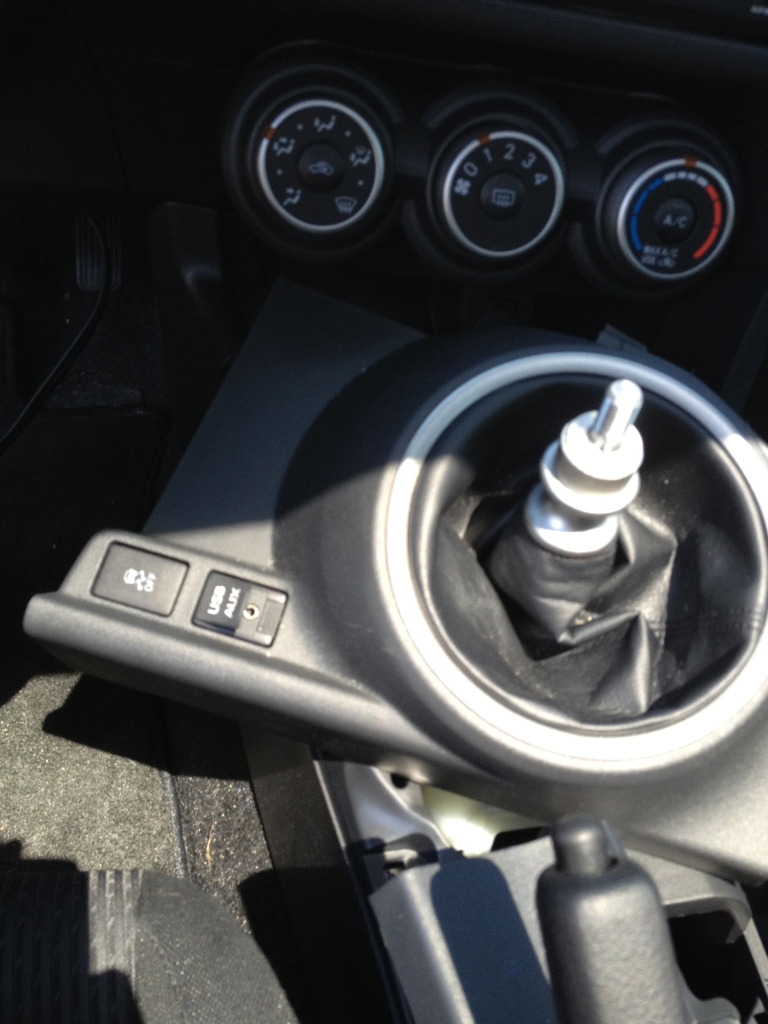
Then remove the cup holders and e-brake cover:
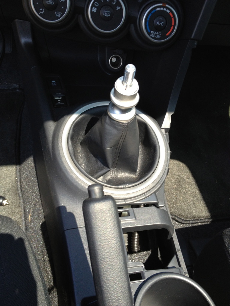
After that lift up on the plastic around the shifter: (I just moved it to the side because you don't really need to take it off)
Lastly remove the plastic piece with the 12v plug
Now that the center console is disassembled, you are ready for the actual fun part, wiring the L.E.D.s!
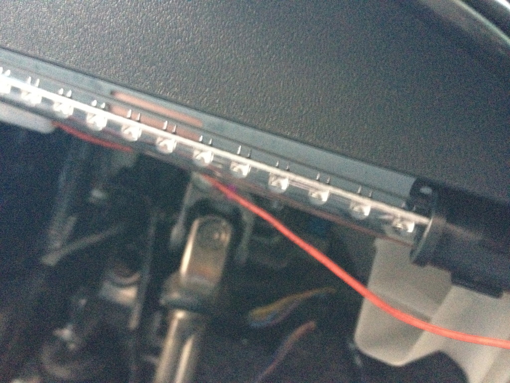
Mount the lights where you want the to be with the wires heading towards the center of the car. My driver's side one is kinda hard to figure out, but its basically shoved between the plastic of the dash
and the metal brace right behind it with a little 3M double sided tape to make sure it stays!
Passenger side was screwed up into the plastic below the glove box.
Passenger:
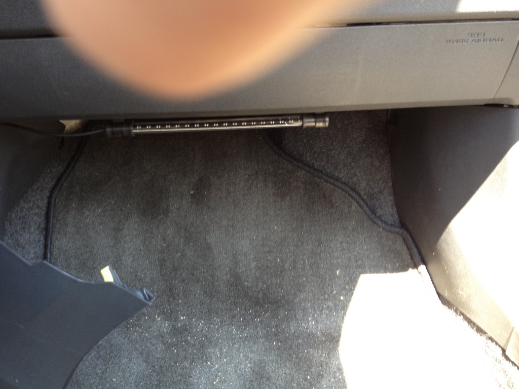
Driver's (hard to tell location so make sure to read the above step):
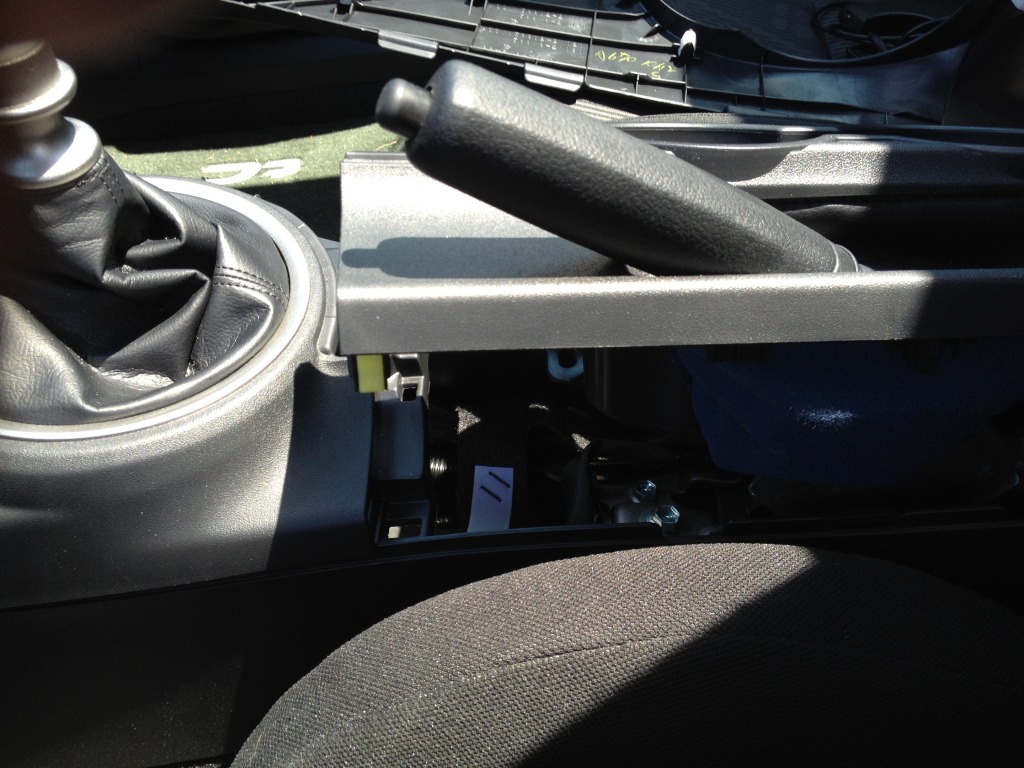
Now you've got the cords and aren't quite sure how to get them into the middle. Well I hate to say it but the new Tc is not like my old 2007.. There is not just a hole behind the dash,
the plastic goes all the way to the fire wall. So with a little searching in the car I found that there are little holes big enough for you to get the wires through.
After that's done, place the controller in the center console and take the power wire (red wire) and snake it out towards the driver side using the same hole you used for the light.
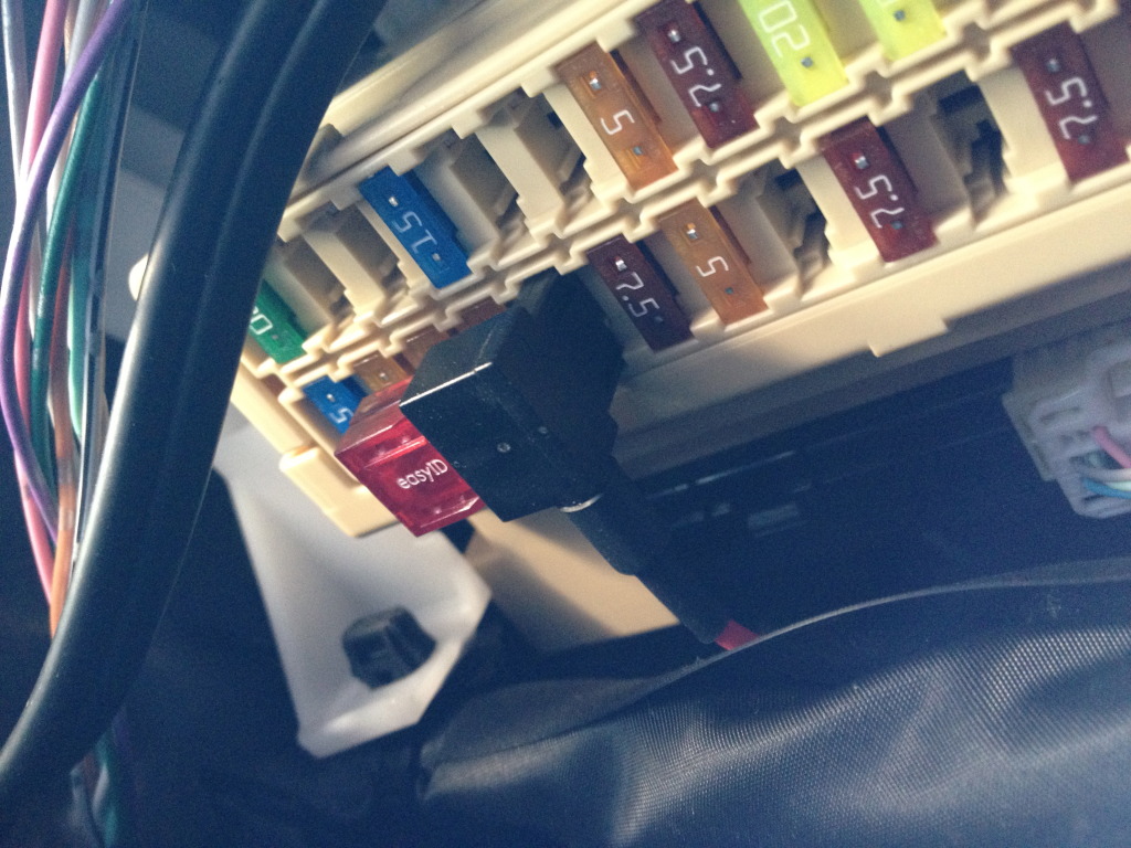
Use one of the electrical connectors and splice the positive wire to the add-a-circuit. Open the fuse box and find the 10amp fuse that is closest to the outside of the vehicle and on the firewall side.
Make sure you plug in both 10 amp fuses on the add-a-circuit. (It's labeled tail on the fuse cover)
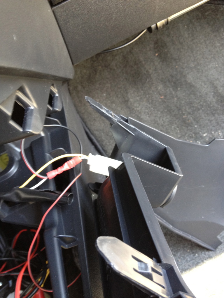
Back in the center console, take the 12v plug and tap into the white wire (give yourself some room by cutting a slit in the plastic cover) about an inch away from the plug, more if you don't trust yourself,
cut the white wire and use your other electrical connector to splice into the ground. When finished it will look something like this:
Plug your lights into the the connector and turn on your head lights. If everything worked out, your new foot well lights will be on! Make sure it works before reassembling the center console,
that way you don't have to remove it again and you can program the lights to do what you want. Also plug something into your 12v just to make sure it still works also.
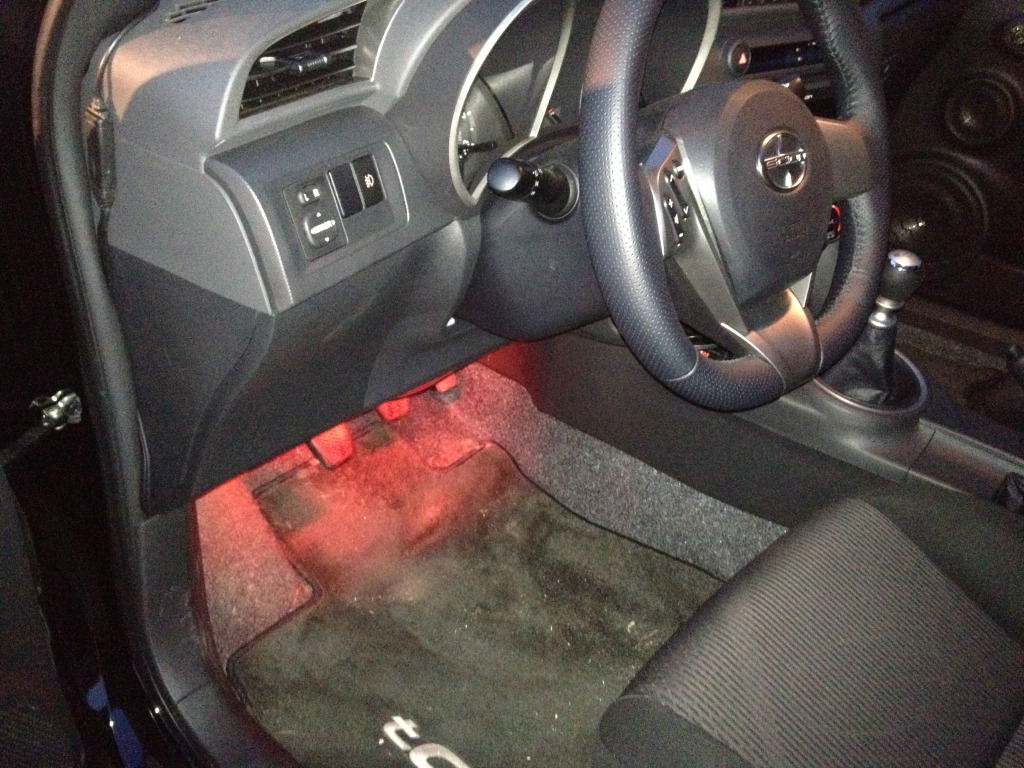
Reassemble and you're done! Should look something like this!
Enjoy guys and good luck!
You're gonna need two of these. (These are the smallest I had but if you can find smaller, I would recommend it.)
So here's how to do it!
First: lay everything out. Figure out where you want everything to go. I wanted my controller hidden because I knew I only wanted a constant glow when the headlights are on so I planned on putting it inside the center console, underneath the plastic covers.
Second: Start disassembling the center console.
You have to remove the passenger side cover first
Then remove the cup holders and e-brake cover:
After that lift up on the plastic around the shifter: (I just moved it to the side because you don't really need to take it off)
Lastly remove the plastic piece with the 12v plug
Now that the center console is disassembled, you are ready for the actual fun part, wiring the L.E.D.s!
Mount the lights where you want the to be with the wires heading towards the center of the car. My driver's side one is kinda hard to figure out, but its basically shoved between the plastic of the dash
and the metal brace right behind it with a little 3M double sided tape to make sure it stays!
Passenger side was screwed up into the plastic below the glove box.
Passenger:
Driver's (hard to tell location so make sure to read the above step):
Now you've got the cords and aren't quite sure how to get them into the middle. Well I hate to say it but the new Tc is not like my old 2007.. There is not just a hole behind the dash,
the plastic goes all the way to the fire wall. So with a little searching in the car I found that there are little holes big enough for you to get the wires through.
After that's done, place the controller in the center console and take the power wire (red wire) and snake it out towards the driver side using the same hole you used for the light.
Use one of the electrical connectors and splice the positive wire to the add-a-circuit. Open the fuse box and find the 10amp fuse that is closest to the outside of the vehicle and on the firewall side.
Make sure you plug in both 10 amp fuses on the add-a-circuit. (It's labeled tail on the fuse cover)
Back in the center console, take the 12v plug and tap into the white wire (give yourself some room by cutting a slit in the plastic cover) about an inch away from the plug, more if you don't trust yourself,
cut the white wire and use your other electrical connector to splice into the ground. When finished it will look something like this:
Plug your lights into the the connector and turn on your head lights. If everything worked out, your new foot well lights will be on! Make sure it works before reassembling the center console,
that way you don't have to remove it again and you can program the lights to do what you want. Also plug something into your 12v just to make sure it still works also.
Reassemble and you're done! Should look something like this!
Enjoy guys and good luck!
Last edited by MR_LUV; Nov 15, 2017 at 02:41 AM.


Senior Member
SL Member
Joined: Mar 2012
Posts: 194
From: SoCal, CA
and is the 9 inch LED good/bright enough for driving? Just asking because they also offer 15 inch for a lil more expensive and i dont know how bright are the 9 inch from the starter kit in real life.

Senior Member
SL Member
Joined: Oct 2011
Posts: 743
From: Huntington Beach, CA
I got a set of lights off ebay for about 6 bucks shipped from hong kong. I think it was an 8 inch strip and I cut it in half. Also, I thought I would mention that you dont need to disassemble the center console, I just pulled the piece closest to the pedals and ran the wires through there (i guess it would be the space under the radio).
This should speed up the install.
Good Luck!
This should speed up the install.
Good Luck!


Senior Member
SL Member
Joined: Mar 2012
Posts: 194
From: SoCal, CA
i really dont know anything about electrical stuff so I was just wondering when you mentioned about using and "electrical connector and splice the positive wire to the add-a-circuit wire", does that mean to take the control box red wire and put the wire into one side of the electrical connector and put the add a circuit pigtail wire into the other side of the connector and use something to squeeze the connector tight? Also the pigtail from the add-a-circuit is pretty thick, how do we "splice" these two together? Thanks!
Senior Member
SL Member
Joined: Oct 2011
Posts: 743
From: Huntington Beach, CA
I see your using a different LED strip, but mine had a positive and a negative wire, I just did the add-a-circuit to the positive and the negative just goes to ground (i.e. find a screw that screws into metal. It took a while, but if you look up, past the fuse box, there is one or two there.

Thread Starter
Senior Member
SL Member
Joined: Nov 2011
Posts: 292
From: New York
i really dont know anything about electrical stuff so I was just wondering when you mentioned about using and "electrical connector and splice the positive wire to the add-a-circuit wire", does that mean to take the control box red wire and put the wire into one side of the electrical connector and put the add a circuit pigtail wire into the other side of the connector and use something to squeeze the connector tight? Also the pigtail from the add-a-circuit is pretty thick, how do we "splice" these two together? Thanks!
Senior Member
SL Member
Joined: Mar 2012
Posts: 194
From: SoCal, CA
do i need to cut any part from the add-a circuit since it looks so much bigger or is it possible to shove the whole wire into the electrical connector?
Thread Starter
Senior Member
SL Member
Joined: Nov 2011
Posts: 292
From: New York
You need to cut the insulation so that you have some copper exposed. You only need like 1/4 inch copper exposed at the most. You're just trying to make some connection between the wire, the metal connection in the electrical connector, and the other wire. Hope that helps.
Senior Member
SL Member
Joined: Mar 2012
Posts: 194
From: SoCal, CA
So what about the add a circuit? did you purchase it from the same site as the starter kit? They have it for sale and it comes with a 4 AMP fuse with the normal and the mini add a circuit. Does the 2 add a circuit have any difference or is there a specific one i need? And instead of using the 4 amp fuse, you used a 10 amp fuse instead. How much amp will these footwell LEDs use? btw, sorry for so much question.
Senior Member
SL Member
Joined: Mar 2012
Posts: 194
From: SoCal, CA
Also, you hid your control box under the central console. If i didnt want to hide it there, and i want to hide it on the side of the pedal instead (like disaster stated) how can i hide the wires going to the drivers and passenger side to light up the LEDs? or how did you hide the wires from control box all the way to the LEDs? thanks!
Thread Starter
Senior Member
SL Member
Joined: Nov 2011
Posts: 292
From: New York
When I bought the kit, they stated that you needed at least a 10 amp fuse. That has since changed to a 4 amp fuse (just checked) You should still be good using a 10 amp fuse and the fuse holder i listed.
I used a different add-a-circuit than the one that you can include with the kit, only because I ordered the standard size add-a-circuit not realizing that our cars require the mini version. The mini version is exactly what we need.
If you want the controller by the pedals (like disaster stated), the positive and ground wires are attached when you get the kit. I simply split the two wires at the seam because I knew I wanted the controller hidden. If you want it by the pedals then don't split them and wire the ground wire near one of the screws by clutch/brake.
Senior Member
SL Member
Joined: Mar 2012
Posts: 194
From: SoCal, CA
Can i ask how did you hide the wire going from your center console all the way to the driver and passenger side? I havent looked at my car yet but from what im just wondering, I dont know where to hide the wire if I were to hide the control box by the pedals. It seems easy to hide it for the driver side since its like RIGHT THERE, but with wires going all the way to the passenger side? im a little confused how to hide the wires thru there. :\

When I bought the kit, they stated that you needed at least a 10 amp fuse. That has since changed to a 4 amp fuse (just checked) You should still be good using a 10 amp fuse and the fuse holder i listed.
I used a different add-a-circuit than the one that you can include with the kit, only because I ordered the standard size add-a-circuit not realizing that our cars require the mini version. The mini version is exactly what we need.
If you want the controller by the pedals (like disaster stated), the positive and ground wires are attached when you get the kit. I simply split the two wires at the seam because I knew I wanted the controller hidden. If you want it by the pedals then don't split them and wire the ground wire near one of the screws by clutch/brake.
I used a different add-a-circuit than the one that you can include with the kit, only because I ordered the standard size add-a-circuit not realizing that our cars require the mini version. The mini version is exactly what we need.
If you want the controller by the pedals (like disaster stated), the positive and ground wires are attached when you get the kit. I simply split the two wires at the seam because I knew I wanted the controller hidden. If you want it by the pedals then don't split them and wire the ground wire near one of the screws by clutch/brake.
Sent from my DROIDX using Tapatalk 2

Junior Member
Joined: Jan 2013
Posts: 4
Possible to get these and set them up to a switch to where they are off when the doors are closed and then when you open them it turns them on? It would work much like the switch on your fridge. haha. Thats what I'm going to do.

Junior Member
Joined: May 2009
Posts: 16
From: CHESTERFIELD, VA
To do this you have to make sure that you have a good enough current running but you can tap into the wires that power on the dome lights when you open the doors you'll jsut have to get a wire tap and find a way to run into it.