


New tc2 owner


Thread Starter
Member
SL Member
Joined: Apr 2012
Posts: 58
 New tc2 owner
Hey guys. Picked up my 2012 metallic grey tc2 6spd in March, my first brand new car! I was originally looking at used cars around $16-18k, but fell in love with the tC and was able to score great financing through Toyota. 
It has:
-TRD quickshifter
-Fog lights
-Scion lower door decal
-TRD shift **** (hate it, but the dealer didn't charge for it since it was installed when I test drove the car. Anyone want one?)
-TRD wheel locks
-Floor/cargo mats
To come:
-Tint (next week)
-Redlinegoods shift boot and Momo shift ****
-Lowbeam 5000k HIDs
-Maybe lowering springs?
A picture from work. Needs a detail, but decently clean:
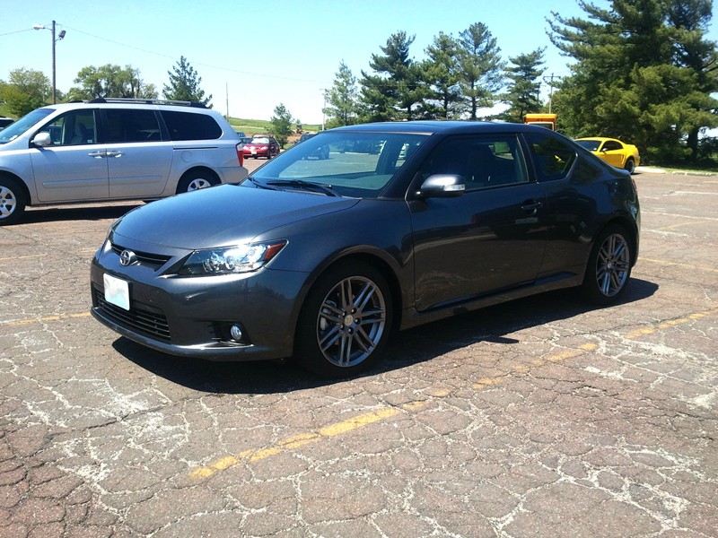
Looking forward to being part of the community!
-Cody
It has:
-TRD quickshifter
-Fog lights
-Scion lower door decal
-TRD shift **** (hate it, but the dealer didn't charge for it since it was installed when I test drove the car. Anyone want one?)
-TRD wheel locks
-Floor/cargo mats
To come:
-Tint (next week)
-Redlinegoods shift boot and Momo shift ****
-Lowbeam 5000k HIDs
-Maybe lowering springs?
A picture from work. Needs a detail, but decently clean:
Looking forward to being part of the community!
-Cody


Thread Starter
Member
SL Member
Joined: Apr 2012
Posts: 58
Thanks for the responses
I'm nearing the end of college, and I plan on keeping this car for (hopefully) the next 5+ years. So I want to keep it as 'solid' as possible. I was bit by the modding bug on my last car (a '97 Maxima 5spd) and needless to say, by the time I sold it things were breaking and making funny noises... so I'd like to keep her relatively close to stock.
In addition to what's listed in the OP, I'd like to fix the laggy throttle response. I'm an electrical engineering major, and I'm looking into designing a simple, low-cost fix for the tC as an alternative to the multiple-hundred-dollar products currently available. Any input here would be appreciated, as I have a lot of reading to do.
I'm nearing the end of college, and I plan on keeping this car for (hopefully) the next 5+ years. So I want to keep it as 'solid' as possible. I was bit by the modding bug on my last car (a '97 Maxima 5spd) and needless to say, by the time I sold it things were breaking and making funny noises... so I'd like to keep her relatively close to stock.
In addition to what's listed in the OP, I'd like to fix the laggy throttle response. I'm an electrical engineering major, and I'm looking into designing a simple, low-cost fix for the tC as an alternative to the multiple-hundred-dollar products currently available. Any input here would be appreciated, as I have a lot of reading to do.

Senior Member


SL Member
Joined: Jan 2008
Posts: 315
From: Houston, TX and Cleveland, OH
Welcome to the boards.
Since you're an electrical engineer...
The way the drive by wire system works is that there is an accelerator pedal position sensor. This sensor converts the amount of depression of the accelerator pedal into an electrical signal which in turn tells the computer how much to open the throttle body.
The way the TWP, Weapon-R, etc etc. works is to smooth the relationship between the electrical signal and the percentage the throttle body is opened.
On the tc1, if you graph the voltage (generated by the position sensor) on the X-axis and graph the percentage of how much the throttle body is open on the Y-axis, you'll get an exponential curve.
With the old cable throttle body assemblies, the position of the pedal is a linear regression with the amount the throttle body is opened.
So... essentially all the throttle body controllers do is to adjust the voltage output by the position sensor before it feeds back and adjusts the opening of the throttle body.
:D
Since you're an electrical engineer...
The way the drive by wire system works is that there is an accelerator pedal position sensor. This sensor converts the amount of depression of the accelerator pedal into an electrical signal which in turn tells the computer how much to open the throttle body.
The way the TWP, Weapon-R, etc etc. works is to smooth the relationship between the electrical signal and the percentage the throttle body is opened.
On the tc1, if you graph the voltage (generated by the position sensor) on the X-axis and graph the percentage of how much the throttle body is open on the Y-axis, you'll get an exponential curve.
With the old cable throttle body assemblies, the position of the pedal is a linear regression with the amount the throttle body is opened.
So... essentially all the throttle body controllers do is to adjust the voltage output by the position sensor before it feeds back and adjusts the opening of the throttle body.
:D

Thread Starter
Member
SL Member
Joined: Apr 2012
Posts: 58
Welcome to the boards.
Since you're an electrical engineer...
The way the drive by wire system works is that there is an accelerator pedal position sensor. This sensor converts the amount of depression of the accelerator pedal into an electrical signal which in turn tells the computer how much to open the throttle body.
The way the TWP, Weapon-R, etc etc. works is to smooth the relationship between the electrical signal and the percentage the throttle body is opened.
On the tc1, if you graph the voltage (generated by the position sensor) on the X-axis and graph the percentage of how much the throttle body is open on the Y-axis, you'll get an exponential curve.
With the old cable throttle body assemblies, the position of the pedal is a linear regression with the amount the throttle body is opened.
So... essentially all the throttle body controllers do is to adjust the voltage output by the position sensor before it feeds back and adjusts the opening of the throttle body.
:D
Since you're an electrical engineer...
The way the drive by wire system works is that there is an accelerator pedal position sensor. This sensor converts the amount of depression of the accelerator pedal into an electrical signal which in turn tells the computer how much to open the throttle body.
The way the TWP, Weapon-R, etc etc. works is to smooth the relationship between the electrical signal and the percentage the throttle body is opened.
On the tc1, if you graph the voltage (generated by the position sensor) on the X-axis and graph the percentage of how much the throttle body is open on the Y-axis, you'll get an exponential curve.
With the old cable throttle body assemblies, the position of the pedal is a linear regression with the amount the throttle body is opened.
So... essentially all the throttle body controllers do is to adjust the voltage output by the position sensor before it feeds back and adjusts the opening of the throttle body.
:D

Senior Member
SL Member
Joined: Sep 2011
Posts: 732
From: Washington, DC
you can find diagrams on toyotapartsoverstock.com . idk if you're looking for a more detailed book.


Senior Member
SL Member
Joined: Sep 2011
Posts: 180
From: STL


Senior Member
SL Member
Joined: Jan 2008
Posts: 315
From: Houston, TX and Cleveland, OH
Not sure if people understood your questions.... but...
Not really sure that there's a diagram for this. Even in the tech service manuals. Of course I am going off of the Tech manuals that are available for the tC1.
The position sensor is a modular part that comes directly from the Toyota factory. As a result this is a part that you buy from Toyota. The position sensor is manufactured at w/e toyota facility manufacturers these parts. If for w/e reason your position sensor fails... you simply replace that assembly at the dealership or at your own auto shop.
(Again this is how it works on the tC1 anyways.)
The diagrams that you speak of... the only thing that I can find is the stuff that discusses the parts list of what part numbers are what. Also, the assembly of the parts.
@the Jiggavolt.... to answer your question, the graph that you are looking for is like the following...
http://www.blitzpowerusa.com/product...n/throcon.html
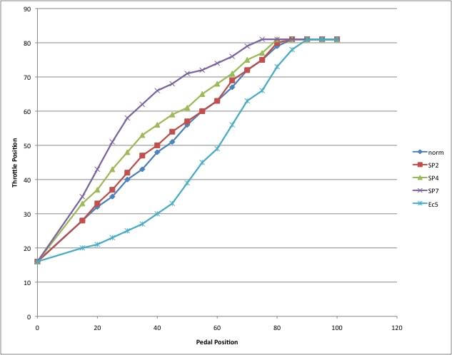
The image below is representative of the TWP Electronic Throttle Controller (not from me).
Original discussion is found here: https://www.scionlife.com/forums/sho...tle+controller
https://www.scionlife.com/forums/sho...tle+controller
If you note the picture, you'll see how it adjusts it to react more like that of a cable throttle.
I believe that it is the exponential curve regression that causes that throttle lag.
On that note... the way I took data for my own personal use is by using the TWP Throttle Controller. I took various readings in set increments to determine the voltage generated at given percentages of depression. Then compared that data to the percentage of how much the throttle body is open.
Each car though it is using a modular assembly, the different voltages read varies from car to car. This is why when you buy a throttle controller, it will ask you to calibrate it by keeping the pedal un-depressed to get a voltage and then fully depressed to again, get another voltage. Once the controller is calibrated for the max and min voltage outputs, you can choose your setting as shown in the graphs.
The position sensor is a modular part that comes directly from the Toyota factory. As a result this is a part that you buy from Toyota. The position sensor is manufactured at w/e toyota facility manufacturers these parts. If for w/e reason your position sensor fails... you simply replace that assembly at the dealership or at your own auto shop.
(Again this is how it works on the tC1 anyways.)
@the Jiggavolt.... to answer your question, the graph that you are looking for is like the following...
http://www.blitzpowerusa.com/product...n/throcon.html
The image below is representative of the TWP Electronic Throttle Controller (not from me).
Original discussion is found here: https://www.scionlife.com/forums/sho...tle+controller
https://www.scionlife.com/forums/sho...tle+controller
If you note the picture, you'll see how it adjusts it to react more like that of a cable throttle.
I believe that it is the exponential curve regression that causes that throttle lag.
On that note... the way I took data for my own personal use is by using the TWP Throttle Controller. I took various readings in set increments to determine the voltage generated at given percentages of depression. Then compared that data to the percentage of how much the throttle body is open.
Each car though it is using a modular assembly, the different voltages read varies from car to car. This is why when you buy a throttle controller, it will ask you to calibrate it by keeping the pedal un-depressed to get a voltage and then fully depressed to again, get another voltage. Once the controller is calibrated for the max and min voltage outputs, you can choose your setting as shown in the graphs.
Thread Starter
Member
SL Member
Joined: Apr 2012
Posts: 58
Great info, thank you! From reading about the Sprint Booster, the exponential relation does appear to be the culprit. Undoubtedly engineered that way for less experienced manual transmission drivers.
If I can get a sunny day this weekend, I'm going to take some measurements of my own. If it keeps raining, I'll start working on a little microcontroller circuit with a input/output voltage map
If I can get a sunny day this weekend, I'm going to take some measurements of my own. If it keeps raining, I'll start working on a little microcontroller circuit with a input/output voltage map
