
My eBay header project :)! (Includes DIY info)


 !
!Unfortunately, I haven't even been able to start the engine yet
Still, on the positive side, the delay gave me another day to define and collect the hardware I need for my modified dip stick mount and the 'S'-pipe to header connection. For some reason, I seem to have more installation complications than Roller_Toaster. But, not important, it's just this extended delay due to the rear O2 sensor that's a pain

Sorry to hear about all the hiccups in your install, hopefully it all comes together soon!
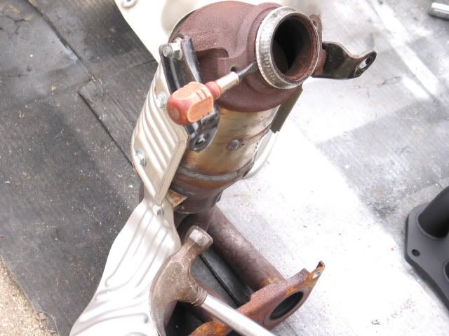
For my dipstick, I simply flattened the "lipped" part of the mounting flange with a hammer and turned it 90 degrees, then bolted it back on.
For my dipstick, I simply flattened the "lipped" part of the mounting flange with a hammer and turned it 90 degrees, then bolted it back on.
I tried rotating the dip stick 90 degrees to the left, but there was still too little clearance to install or remove the header. I ended up making a short aluminum bracket to shift the mount forward 3/4", then a dipstick left rotation of 45 degrees gives me a good result. That's what the last photo shows -- it was a test fit. It's still close enough that I need to protect the header finish with a towel putting it in or taking it out, but at least it's reasonable.
The O2 Sensor tap arrived today and I was finally able to finish my project. I spent a little time driving (in traffic  ) and I like it -- a 4-2-1 would probably have been better, but I think this will do just fine ! I took a pile of photos and so here you go
  !
!
First the tear down --

The exhaust manifold is secured by four bolts, two at the top, two at the bottom sides (12mm tool).


The O2 sensor plug is released by pressing in a tab at the right rear side of the socket -- a little stiff, but it works. The rear sensor is released the same way.

The cable clamp is released by squeezing the two levers inward -- I used a pair of pliers. With the sensor harness fully free, the sensor itself can be removed either with a 22mm wrench or an O2 Sensor removal tool -- basically a deep socket with a narrow slot down the side for the harness to exit (see the below "build" section for a photo).

I tried a ratchet and a combination wrench but had best results with a deep offset crescent wrench (12mm tool). I had to move the cable bundle to the left to get sufficient room for the leftmost nut.


The two exhaust manifold side support bolts are a little awkward to get out, but I just tried different combinations of sockets and adapters until I found something that fit (14mm tool).

I raised the nose from the center jacking point and then lowered it onto jack stands so it rests on the pair of large bolt heads on each side.

'S'-Pipe spring bolt removal -- takes a lot of turns (14mm tool).
The lower exhaust manifold gasket can be removed by working around it carefully levering with a screwdriver -- tap the screwdriver with a hammer as needed. Be careful not to damage it.
! I took a pile of photos and so here you go !First the tear down --
The exhaust manifold is secured by four bolts, two at the top, two at the bottom sides (12mm tool).
The O2 sensor plug is released by pressing in a tab at the right rear side of the socket -- a little stiff, but it works. The rear sensor is released the same way.
The cable clamp is released by squeezing the two levers inward -- I used a pair of pliers. With the sensor harness fully free, the sensor itself can be removed either with a 22mm wrench or an O2 Sensor removal tool -- basically a deep socket with a narrow slot down the side for the harness to exit (see the below "build" section for a photo).
I tried a ratchet and a combination wrench but had best results with a deep offset crescent wrench (12mm tool). I had to move the cable bundle to the left to get sufficient room for the leftmost nut.
The two exhaust manifold side support bolts are a little awkward to get out, but I just tried different combinations of sockets and adapters until I found something that fit (14mm tool).
I raised the nose from the center jacking point and then lowered it onto jack stands so it rests on the pair of large bolt heads on each side.
'S'-Pipe spring bolt removal -- takes a lot of turns (14mm tool).
The lower exhaust manifold gasket can be removed by working around it carefully levering with a screwdriver -- tap the screwdriver with a hammer as needed. Be careful not to damage it.
Last edited by TrevorS; Apr 20, 2011 at 02:52 AM. Reason: added info
Unfortunately, I had a rear O2 sensor problem (cross threaded by Toyota at the factory) and was forced to remove the 'S'-Pipe as well -- shouldn't really have been necessary

Repair required running an 18MMx1.50 tap through the O2 sensor bung, and I also ran a 10mmx1.25 die over the 'S'-Pipe to "scuba" bolts to clean them. Fortunately, after some cleanup (grinder and file), the O2 sensor was still usable. BTW -- if you want to just clean the thread (carbon, oxidation, mild thread damage), you can get an O2 Sensor Thread Chaser that does a nice job.
Repair required running an 18MMx1.50 tap through the O2 sensor bung, and I also ran a 10mmx1.25 die over the 'S'-Pipe to "scuba" bolts to clean them. Fortunately, after some cleanup (grinder and file), the O2 sensor was still usable. BTW -- if you want to just clean the thread (carbon, oxidation, mild thread damage), you can get an O2 Sensor Thread Chaser that does a nice job.
Last edited by TrevorS; Apr 20, 2011 at 05:33 PM. Reason: added info
Then the build --


Here are the OE exhaust manifold to 'S'-Pipe coupling bolts with the 10MMx1.25 nuts needed to secure them to the header. Ignore the pictured split washers, there isn't room for them on the installed bolts.
Also shown is a 1/8" thick aluminum bracket with 1/4" holes centered 3/4" apart that relocates the dipstick straight forward toward the radiator to provide header install/removal clearance. The OE 6MMx1.00x16 bolt secures the back of the bracket to the OE dipstick mount. A 6MMx1.00x20 bolt with matching nut and split washer is used to secure the dipstick to the underside of the bracket. The dipstick itself should be rotated clockwise 45 to 50 degrees.

Here's the installed bracket and dipstick as described above. Also shown is the cylinder head exhaust gasket face after a good cleaning. The cleaning is important since you don't want any debris trapped between the gasket and the head.

Here's the OE stainless steel exhaust manifold gasket after I cleaned as much of the OE exhaust manifold rust debris from it as I could. The only reason this matters is because having leveled the header gasket face, it makes sense to reuse the OE gasket (it helps conduct heat from the head which is good for cooling). If I hadn't leveled the header flange, I'd use the gasket that came with the header instead.


Here is the OE gasket preserving the original orientation. Again, if the header flange hasn't been leveled, use the gasket supplied with the header.
Next comes header install and bolt/nut starting and tightening, however, don't actually tighten anything until all the piping fasteners are started. Carefully position the header on the studs and give the head flange nuts a few turns, but leave a good gap under each. If the 'S'-Pipe was removed, position it and start it's rear bolts, but leave them loose (if the 'S'-Pipe wasn't removed, it could make install a little easier if you loosen the rear bolts anyway). Now, carefully align the 'S'-Pipe entry port with the header lower flange. Once they're in correct position, finger tighten the head flange nuts, and then start the spring bolts as described below. When all fasteners are started, final tightening should be in order of header nuts, spring bolts, and lastly, 'S'-Pipe rear bolts.

When tightening the header nuts, start at the center and bounce from side-to-side working outward and tightening in stages. Pressure should be applied gradually across the entire flange, finishing at the outermost two nuts at each stage.

I forgot to take a photo of removing an O2 sensor, so here's one showing the standard tool for removal or tightening. There's a slot on the side for the harness.
Note -- the harness should be fully free of attachments before screwing or unscrewing the sensor.


It was something of a challenge to reinstall the OE bolts with their springs, but it wasn't too bad, and it's definitely worth doing to avoid the stress of having the engine through and including the "scuba" a rigid assembly -- which is what bolts alone would create. The header to 'S'-Pipe coupling needs to be able to flex, hence the springs.
My approach was to "start" the least well aligned of the two bolts first, then the other. By "start" I mean ratchet the bolt far enough into the header flange that the 10mm threads emerge and the nut can be "started" -- but don't tighten yet. I accomplished this by positioning the bolt through the spring and as far into the header flange as I could by pushing the bolt with a 1/2" ratchet and pressing sideways on the ratchet as needed to engage the thread on the edge of the header flange hole. Then, maintaining sideways pressure, ratchet the bolt gradually into the hole until the 10mm portion of the thread emerges and you can start the nut with your other hand (be careful not to cross thread). Once that one's done, do the same thing with the other. When final tightening, position a crescent wrench over the nuts one at a time and tighten their respective bolts (they have built in stops).
Note -- during bolt install, be careful to keep the bolt thread engaged with the header flange hole until the nut is started, if sideways pressure is released too soon, the spring is likely to pop the bolt right back out again.

Be sure not to position the sensor too close to other car components, just in case it might hit during vehicle operation. Also, you might want to position it so that you can get a tool on it later in case there's a need to remove it. It's a good idea to use anti-seize compound on both the CEL Eliminator and sensor threads, but be careful not to get any compound on the sensor tip. That goes for the front sensor too.
Note -- Be very careful not to cross-thread -- it's easy to do and so, if there's any doubt at all, back it out and try again (this applies to both Eliminator and sensor).

Hopefully, it wasn't necessary to remove the 'S'-Pipe, but if it was, it's a good idea to clean the bolt threads (10MMx1.25) and re-install with anti-seize compound.
=======================================================
All done!

Time to cure the header paint and start driving!
Here are the OE exhaust manifold to 'S'-Pipe coupling bolts with the 10MMx1.25 nuts needed to secure them to the header. Ignore the pictured split washers, there isn't room for them on the installed bolts.
Also shown is a 1/8" thick aluminum bracket with 1/4" holes centered 3/4" apart that relocates the dipstick straight forward toward the radiator to provide header install/removal clearance. The OE 6MMx1.00x16 bolt secures the back of the bracket to the OE dipstick mount. A 6MMx1.00x20 bolt with matching nut and split washer is used to secure the dipstick to the underside of the bracket. The dipstick itself should be rotated clockwise 45 to 50 degrees.
Here's the installed bracket and dipstick as described above. Also shown is the cylinder head exhaust gasket face after a good cleaning. The cleaning is important since you don't want any debris trapped between the gasket and the head.
Here's the OE stainless steel exhaust manifold gasket after I cleaned as much of the OE exhaust manifold rust debris from it as I could. The only reason this matters is because having leveled the header gasket face, it makes sense to reuse the OE gasket (it helps conduct heat from the head which is good for cooling). If I hadn't leveled the header flange, I'd use the gasket that came with the header instead.
Here is the OE gasket preserving the original orientation. Again, if the header flange hasn't been leveled, use the gasket supplied with the header.
Next comes header install and bolt/nut starting and tightening, however, don't actually tighten anything until all the piping fasteners are started. Carefully position the header on the studs and give the head flange nuts a few turns, but leave a good gap under each. If the 'S'-Pipe was removed, position it and start it's rear bolts, but leave them loose (if the 'S'-Pipe wasn't removed, it could make install a little easier if you loosen the rear bolts anyway). Now, carefully align the 'S'-Pipe entry port with the header lower flange. Once they're in correct position, finger tighten the head flange nuts, and then start the spring bolts as described below. When all fasteners are started, final tightening should be in order of header nuts, spring bolts, and lastly, 'S'-Pipe rear bolts.
When tightening the header nuts, start at the center and bounce from side-to-side working outward and tightening in stages. Pressure should be applied gradually across the entire flange, finishing at the outermost two nuts at each stage.
I forgot to take a photo of removing an O2 sensor, so here's one showing the standard tool for removal or tightening. There's a slot on the side for the harness.
Note -- the harness should be fully free of attachments before screwing or unscrewing the sensor.
It was something of a challenge to reinstall the OE bolts with their springs, but it wasn't too bad, and it's definitely worth doing to avoid the stress of having the engine through and including the "scuba" a rigid assembly -- which is what bolts alone would create. The header to 'S'-Pipe coupling needs to be able to flex, hence the springs.
My approach was to "start" the least well aligned of the two bolts first, then the other. By "start" I mean ratchet the bolt far enough into the header flange that the 10mm threads emerge and the nut can be "started" -- but don't tighten yet. I accomplished this by positioning the bolt through the spring and as far into the header flange as I could by pushing the bolt with a 1/2" ratchet and pressing sideways on the ratchet as needed to engage the thread on the edge of the header flange hole. Then, maintaining sideways pressure, ratchet the bolt gradually into the hole until the 10mm portion of the thread emerges and you can start the nut with your other hand (be careful not to cross thread). Once that one's done, do the same thing with the other. When final tightening, position a crescent wrench over the nuts one at a time and tighten their respective bolts (they have built in stops).
Note -- during bolt install, be careful to keep the bolt thread engaged with the header flange hole until the nut is started, if sideways pressure is released too soon, the spring is likely to pop the bolt right back out again.
Be sure not to position the sensor too close to other car components, just in case it might hit during vehicle operation. Also, you might want to position it so that you can get a tool on it later in case there's a need to remove it. It's a good idea to use anti-seize compound on both the CEL Eliminator and sensor threads, but be careful not to get any compound on the sensor tip. That goes for the front sensor too.
Note -- Be very careful not to cross-thread -- it's easy to do and so, if there's any doubt at all, back it out and try again (this applies to both Eliminator and sensor).
Hopefully, it wasn't necessary to remove the 'S'-Pipe, but if it was, it's a good idea to clean the bolt threads (10MMx1.25) and re-install with anti-seize compound.
=======================================================
All done!
Time to cure the header paint and start driving
!
Last edited by TrevorS; Apr 20, 2011 at 06:09 PM. Reason: added more info
!It's gradually occurring to me as distinctly different from before -- a growing impression. It's a little awkward since several days went by with the car dead (thanks to the rear O2 sensor problem), and so it's not as back-to-back as I'd expected.
I've only driven it a couple days so far and all local running in traffic with a brief max speed of about 40 mph, so I'm not sure what one should expect. The car already had a pretty low engine and exhaust pitch following install of a smooth-bore TBS, but now it becomes very low growly even at modest rpm and acceleration. In terms of feel, it seems to pull a little more forcefully in tandem with the growl, and there again appears to be an improvement in speed holding and acceleration up slopes. I actually felt modestly pressed back into the seat in third gear from a stop light with very modest throttle.
I guess my interpretation is exhaust breathing is very much improved, and it complements previous improvements I've made in intake breathing. It very much reminds me of the change in feel of my Eclipse as I made improvements to its intake and exhaust breathing. I need more time to evaluate it, but I'm liking it so far
!
Yeah, the price was very important to me -- both due to lack of funds, and to lack of confidence it'll pass local inspection without the pre-cat. Still, I was very curious as to the effect of improving exhaust flow after spending mucho time working on intake flow. I'll tell you one thing, the difference between the way the car drives now and when I originally drove it off the lot is so tremendous, I'd say the original is at most barely recognizable (same transmission ratios). Of course, that's not so uncommon among SL members !
!
I'm wondering a little about the output separator plate positioning. I would have expected it to separate cylinders 1 and 4 from 2 and 3, but it does the reverse. Seems odd to me given standard cylinder firing sequence, but I don't know for sure what's typical for headers.


They're the same! Can anybody explain that 1-2/3-4 pipe organization at the collector
 ?
?
Senior Member
Scikotics
SL Member
Joined: Aug 2009
Posts: 319
From: Central Jerz
but Trev just brought a question to mind...where I live they do Emissions testing only...so although there is a solution for the CEL and a way to trick the ECU will this really alter our emissions that much where it would cause a fail at inspections??
I'm expecting the pre-cat contribution to emissions control to be overshadowed by that of the main cat in the "scuba" once its catalyst gets to operating temperature. If that's the case, then the Eliminator will prevent any OBDII worries. If that's not the case, then the solution would be to temporarily switch the OE exhaust manifold back in (probably can leave the Eliminator installed). Guess I'll find out come Jan 2013  .
.

As I understand it the divided collector desgin makes it work more like a 4-2-1 design than a 4-1. The goal being to increase the scavenging effect by keeping the indivdual cylinder pulses separated longer. At least that's the best explanation I have based on my limited knowledge of header design.
Even if they use a tail-pipe sniffer, chances are that you'd still pass easily. Our exhaust emmisions are so low that even without the primary cat it should still meet state spec's. The biggest concern is if they do a visual imspection to look for modifications.
Senior Member
Scikotics
SL Member
Joined: Aug 2009
Posts: 319
From: Central Jerz
Here in MD they do emmisions testing only but they don't use a exhaust gas sniffer on OBDII vehicles. All they do in MD is plug a OBDII scan tool into the port and look for DTC (digital trouble codes) that can trip a CEL or indicate a problem that might affect vehicle emissions. As long as there are no codes present, you pass. A proper CEL eliminator will prevent any codes from appearing. I passed recently with no cats and a very loud 3" CXR exhaust.
As I understand it the divided collector desgin makes it work more like a 4-2-1 design than a 4-1. The goal being to increase the scavenging effect by keeping the indivdual cylinder pulses separated longer. At least that's the best explanation I have based on my limited knowledge of header design.
Thing is, the 4-2-1 properly pairs the 1,4 and 2,3 cylinders in the "2" section. Those piston pairs move together and fire two strokes apart, thus giving balanced scavenging behavior. To team up 1,2 and 3,4 makes no sense to me since those pistons fire alternately one stroke apart and three strokes apart -- completely out of balance. I just don't get it -- unless the divider is actually just to strengthen the collector and the pairing is arbitrary. Perhaps I should try asking Strup and see what they say.
Senior Member
Scikotics
SL Member
Joined: Aug 2009
Posts: 319
From: Central Jerz
hmmm now that you mention it Fred they do make you open your hood up...although they just check emissions....wonder if there is a way to get the heat shield back on with the aftermarket header just for inspection...kinda hard to tell if its been tampered if its covered by the heat shield....haha (doubt that would work tho)
anyways once again thanks Fred!
anyways once again thanks Fred!
It wouldn't be hard to have some mounting tabs welded on the header to mount the oe heat shield. I bet they'd never notice the difference.
Good luck and you're welcome.