
LED Swap (07 HVAC w/Circuit Mod)


Thread Starter
Senior Member
Scikotics
SL Member
Joined: Nov 2004
Posts: 9,731
From: Minneapolis, MN
***Edited for a typo and to add some info here and there***
FYI: Due to a good number of stock HVAC failures on the 07 tC, I feel I should warn that if you have had ANY issue with your stock HVAC lighting or a faint burning smell it should be looked at by the dealer. There have been many lately posting on these issues on the stock board, so you dont want to go modding it if you think these issues may be present.
This is the newest incarnation of the HVAC mod for running blue, green or white LEDs.. If you are running red LEDs or are only swapping the gauge LEDS, then you do not need to perform this mod. As always, I take no responsibility for anything you may do to damage the board. The mod itself works, but you always take a small risk of damaging something when you begin modding. I have 6 years of schooling and 2 degrees in the areas of electronics engineering (telecommunications and control systems) and engineering management, for those leary of taking someone on the internets mod and applying it to your baby But like I said, be careful not to damage anything while working. I reccomend taking static precautions since you are working around static sensitive devices, using a soldering iron with proper ESD protection, etc.
Before beginning, it is a good idea to determine if this is a job you want to tackle if you do not have a lot of experience with this. Below is a list of what is involved:
1. De-soldering the LCD for the clock. This is probably one of the more tedious pieces. This takes some patience to do right and can result in a broken LCD, which is replaceable only through purchasing an entire HVAC module. So be careful on this step!
2. De-soldering all LEDs and some surface mount resistors. These parts are very small, so be ready to work with tweezers.
3. Soldering the new parts back in and soldering in the LCD
Tools you will need for this:
1. Soldering iron: 25-30W is plenty. Work quickly if you use a 30W iron. A temperature controlled iron is recommended, but I realize many may not want to spend $150 or so for one of these. You will need a small pointed tip for this (if using Cooper/Weller irons, I recommend an ETO or ETA tip).
2. Solder sucker: You can purchase a cheap one that is heated from Radio Shack or a similar store for around $10. Solder wick works great as well, but if you are not experience using it, the sucker may be a better option
3. Solder: You will need a small gauge solder for this.
4. Tweezers
5. Needle nose pliers: to remove the temp **** lock nut
Parts needed for the 2007 HVAC board
16 - PLCC-2 LEDS (18 if you want to do the gradient effect on the temp ****)
3 � 0805 package 43 Ohm SMT resistors
1 � 0805 package 130 Ohm SMT resistor
1 � 0805 package 420 Ohm SMT resistor
1 � 0805 package 680 Ohm SMT resistor
1 � 0806 package 560 Ohm SMT resistor
1 � SP-3SU package +10V regulator 1.2A rating
Ok, let�s get started.
I don�t recommend this if you are not familiar with or comfortable with soldering and wiring. I won�t go through soldering techniques or disassembling the console, as this has already been covered in these other posts.
https://www.scionlife.com/forums/viewtopic....t=37747&start=0
https://www.scionlife.com/forums/viewtopic....t=61793&start=0
I will focus on the circuit design. I will note one thing though. Be VERY patient with the LCD. Use solder wick and/or a desoldering iron, and move from one end to the other so you are not focusing heat on one area too long. It will seem they will never come loose, but there is solder all the way through, so it takes a while to get it all out. Don�t try removing it until you can see all pins on the bottom move when you wiggle the display.
1. On the front of the board, de-solder the following parts:
a. R302 � Top left side of board, marked in red in Figure 1 below
b. R301 � Left of leds under clock LCD.
c. R305 � upper left of TEMP **** LEDs. Marked in red in Fig 2
d. R306 � lower left of temp ****. Figure 2
e. R307 � lower right of temp ****. Figure 2
f. All LEDs you will be swapping
2. On the back of the board, de-solder the following:
a. R304 � Marked in red in figure 3 below. Top left
b. R303 � Middle-right side. Fig 4 Below
c. IC300 � Middle Right. Figure 4
3. Replace the removed components with the new values listed below:
a. All LEDS removed previously
b. R302: 0805 package 43 Ohm SMT resistor
c. R304: 0805 package 43 Ohm SMT resistor
d. R303: 0805 package 43 Ohm SMT resistor
e. R301 (Clock): 0805package 130 Ohm SMT resistor
f. R305: 0805 package 420 Ohm SMT resistor
g. R306: 0805 package 560 Ohm SMT resistor
h. R307: 0805 package 680 Ohm SMT resistor
i. IC300: SP-3SU package +10V regulator 1.2A rating
4. This is a good time to plug the unit back in and test. Make sure to push all of the buttons and test all functions now so you don�t end up taking it back apart later.
5. Solder the LCD back into place. Be careful to move end to end while soldering so as not to overheat one area.
6. Clean all connections with rubbing alcohol and dry thoroughly
7. Plug in to test once again
8. Re-assemble HVAC module, install and enjoy!
Figure 1
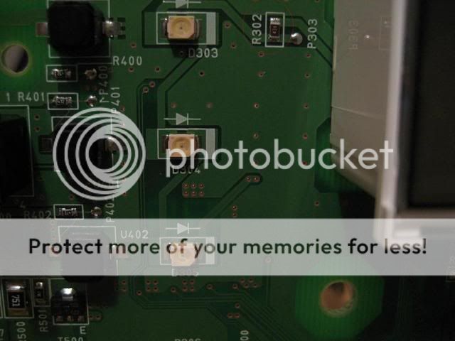
Figure 2

Figure 3

Figure 4

**EDIT** Thanks to Garage1217 for the correct designator for the resistor under the LCD!
FYI: Due to a good number of stock HVAC failures on the 07 tC, I feel I should warn that if you have had ANY issue with your stock HVAC lighting or a faint burning smell it should be looked at by the dealer. There have been many lately posting on these issues on the stock board, so you dont want to go modding it if you think these issues may be present.
This is the newest incarnation of the HVAC mod for running blue, green or white LEDs.. If you are running red LEDs or are only swapping the gauge LEDS, then you do not need to perform this mod. As always, I take no responsibility for anything you may do to damage the board. The mod itself works, but you always take a small risk of damaging something when you begin modding. I have 6 years of schooling and 2 degrees in the areas of electronics engineering (telecommunications and control systems) and engineering management, for those leary of taking someone on the internets mod and applying it to your baby
Before beginning, it is a good idea to determine if this is a job you want to tackle if you do not have a lot of experience with this. Below is a list of what is involved:
1. De-soldering the LCD for the clock. This is probably one of the more tedious pieces. This takes some patience to do right and can result in a broken LCD, which is replaceable only through purchasing an entire HVAC module. So be careful on this step!
2. De-soldering all LEDs and some surface mount resistors. These parts are very small, so be ready to work with tweezers.
3. Soldering the new parts back in and soldering in the LCD
Tools you will need for this:
1. Soldering iron: 25-30W is plenty. Work quickly if you use a 30W iron. A temperature controlled iron is recommended, but I realize many may not want to spend $150 or so for one of these. You will need a small pointed tip for this (if using Cooper/Weller irons, I recommend an ETO or ETA tip).
2. Solder sucker: You can purchase a cheap one that is heated from Radio Shack or a similar store for around $10. Solder wick works great as well, but if you are not experience using it, the sucker may be a better option
3. Solder: You will need a small gauge solder for this.
4. Tweezers
5. Needle nose pliers: to remove the temp **** lock nut
Parts needed for the 2007 HVAC board
16 - PLCC-2 LEDS (18 if you want to do the gradient effect on the temp ****)
3 � 0805 package 43 Ohm SMT resistors
1 � 0805 package 130 Ohm SMT resistor
1 � 0805 package 420 Ohm SMT resistor
1 � 0805 package 680 Ohm SMT resistor
1 � 0806 package 560 Ohm SMT resistor
1 � SP-3SU package +10V regulator 1.2A rating
Ok, let�s get started.
I don�t recommend this if you are not familiar with or comfortable with soldering and wiring. I won�t go through soldering techniques or disassembling the console, as this has already been covered in these other posts.
https://www.scionlife.com/forums/viewtopic....t=37747&start=0
https://www.scionlife.com/forums/viewtopic....t=61793&start=0
I will focus on the circuit design. I will note one thing though. Be VERY patient with the LCD. Use solder wick and/or a desoldering iron, and move from one end to the other so you are not focusing heat on one area too long. It will seem they will never come loose, but there is solder all the way through, so it takes a while to get it all out. Don�t try removing it until you can see all pins on the bottom move when you wiggle the display.
1. On the front of the board, de-solder the following parts:
a. R302 � Top left side of board, marked in red in Figure 1 below
b. R301 � Left of leds under clock LCD.
c. R305 � upper left of TEMP **** LEDs. Marked in red in Fig 2
d. R306 � lower left of temp ****. Figure 2
e. R307 � lower right of temp ****. Figure 2
f. All LEDs you will be swapping
2. On the back of the board, de-solder the following:
a. R304 � Marked in red in figure 3 below. Top left
b. R303 � Middle-right side. Fig 4 Below
c. IC300 � Middle Right. Figure 4
3. Replace the removed components with the new values listed below:
a. All LEDS removed previously
b. R302: 0805 package 43 Ohm SMT resistor
c. R304: 0805 package 43 Ohm SMT resistor
d. R303: 0805 package 43 Ohm SMT resistor
e. R301 (Clock): 0805package 130 Ohm SMT resistor
f. R305: 0805 package 420 Ohm SMT resistor
g. R306: 0805 package 560 Ohm SMT resistor
h. R307: 0805 package 680 Ohm SMT resistor
i. IC300: SP-3SU package +10V regulator 1.2A rating
4. This is a good time to plug the unit back in and test. Make sure to push all of the buttons and test all functions now so you don�t end up taking it back apart later.
5. Solder the LCD back into place. Be careful to move end to end while soldering so as not to overheat one area.
6. Clean all connections with rubbing alcohol and dry thoroughly
7. Plug in to test once again
8. Re-assemble HVAC module, install and enjoy!
Figure 1
Figure 2
Figure 3
Figure 4
**EDIT** Thanks to Garage1217 for the correct designator for the resistor under the LCD!
Senior Member
Scikotics
SL Member
Team ScioNRG
Joined: Jul 2006
Posts: 290
From: Old Bridge, NJ
Very nice, but i wouldnt recomend any amature to preform this procedure. I had Karl from Little ferry NJ do my friends gauges and HVAC and he did hundreds of scions. The LCD clock is the worst part, Karl used a Solder sucker and alot of patience.
IDk if Karl replaced that many resistors but he did a rerouting thing for more voltage. The information you gave with the resistors might be very helpfull.
Still i wouldnt go through this much trouble to do it myself, i rather pay $100 to get it done perfect then worry about breaking parts and buying equipment. I giver you a lot of probs for taking the time to share everything thou
Thread Starter
Senior Member
Scikotics
SL Member
Joined: Nov 2004
Posts: 9,731
From: Minneapolis, MN
I agree that it can be tedious. But I am the one that designed the circuit mod he used on yours.. so I am prepared to do it I I have done a few myself :D This is my newest mod, which makes it much easier.


Senior Member


SL Member
Team ScioNRG
Joined: Mar 2005
Posts: 5,920
From: Staten Island, NY
Originally Posted by engifineer
thanks quiet.
For any parts like this, go to car-part.com. It links to tons of salvages all over the US. You can usually get them for $75 - $100 in good shape.
For any parts like this, go to car-part.com. It links to tons of salvages all over the US. You can usually get them for $75 - $100 in good shape.
where can i order the SMT resistors? is there an online site i could order them all through?
thanks
EDIT
and where can i get one of those regulators?
Thread Starter
Senior Member
Scikotics
SL Member
Joined: Nov 2004
Posts: 9,731
From: Minneapolis, MN
digikey is my preferred vendor for all of the parts.
311-43ARCT-ND RES 43 OHM 1/8W 5% 0805
311-680ARCT-ND RES 680 OHM 1/8W 5% 0805
311-560ARCT-ND RES 560 OHM 1/8W 5% 0805
311-422CCT-ND RES 422 OHM 1/8W 1% 0805
311-422CCT-ND RES 422 OHM 1/8W 1% 0805
311-130ACT-ND RES 130 OHM 1/8W 5% 0805
AN7710SP VOLT REG POS 10V 1.2A SMD SP3SU

I will also be buying in bulk, so you can probably get them through me easilly as well.
311-43ARCT-ND RES 43 OHM 1/8W 5% 0805
311-680ARCT-ND RES 680 OHM 1/8W 5% 0805
311-560ARCT-ND RES 560 OHM 1/8W 5% 0805
311-422CCT-ND RES 422 OHM 1/8W 1% 0805
311-422CCT-ND RES 422 OHM 1/8W 1% 0805
311-130ACT-ND RES 130 OHM 1/8W 5% 0805
AN7710SP VOLT REG POS 10V 1.2A SMD SP3SU
I will also be buying in bulk, so you can probably get them through me easilly as well.

Senior Member

SoCal tC Club
SL Member
Team N.V.S.
Scinergy
Scion Evolution
Joined: Oct 2004
Posts: 15,699
:D
well... if i were to use or find 0805.. yes.. but i'm glad my local Fry's Electronics carries 1206's and (yeah they're ok) NTE products which they probably have, but haven't checked yet, the regulator.
well... if i were to use or find 0805.. yes.. but i'm glad my local Fry's Electronics carries 1206's and (yeah they're ok) NTE products which they probably have, but haven't checked yet, the regulator.
Thread Starter
Senior Member
Scikotics
SL Member
Joined: Nov 2004
Posts: 9,731
From: Minneapolis, MN
You can use the 1206 on both models as well as squall said. The 1206 is slightly big for the 07 and the 0805 is slightly small for the 05/06
The regulator is a slightly different package (smaller) than a standard one. But Fry's may have it.
The regulator is a slightly different package (smaller) than a standard one. But Fry's may have it.
Senior Member
SL Member
Team ScioNRG
Joined: Mar 2005
Posts: 5,920
From: Staten Island, NY
Originally Posted by engifineer
You can use the 1206 on both models as well as squall said. The 1206 is slightly big for the 07 and the 0805 is slightly small for the 05/06
The regulator is a slightly different package (smaller) than a standard one. But Fry's may have it.
The regulator is a slightly different package (smaller) than a standard one. But Fry's may have it.
the same parts that are needed for the 05/06 are the same for the 07's?
also... does this look correct? [all in quantities of 10]
311-43ARCT-ND RES 43 OHM 1/8W 5% 0805 SMD
311-680ARCT-ND RES 680 OHM 1/8W 5% 0805 SMD
311-560ARCT RES 560 OHM 1/8W 5% 0805 SMD
311-422CCT-ND RES 422 OHM 1/8W 1% 0805 SMD
AN7710SP VOLT REG POS 10V 1.2A SMD SP3SU
it also says to contact Digikey about hte 130 ohm resistors... hmmm
Senior Member
SoCal tC Club
SL Member
Team N.V.S.
Scinergy
Scion Evolution
Joined: Oct 2004
Posts: 15,699
hmmm.. that's what i'm concerned about... Fry's might only have the regular size... i couldn't find a cross reference match for NTE online for Panasonic's AN7710SP... but was able for just the AN7710...
Thread Starter
Senior Member
Scikotics
SL Member
Joined: Nov 2004
Posts: 9,731
From: Minneapolis, MN
I actually used 120 on mine. The LCD is a tiny bit brighter than the odometer LCD, but I like it that way. Any 0805 130ohm resistor will work, so you can try a few different part numbers. Some of thier part numbers reflect buying in bulk. Search for 130 OHM 0805 and you should find what you need.
For the 05/06, I reccomend using the 1206, which is the correct size for it. They are a little larger. You can use the 1206 on the 07 as well, but it will extend right to the edge of the pads, so make sure you get good heat contact on the pads when soldering them. I am ****.. so I like to use the stock size
Here is a pic of the 0805 package resistors to give you an idea:
Thread Starter
Senior Member
Scikotics
SL Member
Joined: Nov 2004
Posts: 9,731
From: Minneapolis, MN
For the regulator squall, you will need to look up the pacakge dimensions for both to make sure they match. The one on the board is a little smaller than the average regulator ic. Whats cool about the ones I got from digikey is that the middle leg comes pre-clipped and the leads are already bent. It is a simple swap and solder.
Now, to finish up my other few mods! We are leaving in a little bit for OK (nice 9 hour drive ), so I will talk to you all later!
Now, to finish up my other few mods! We are leaving in a little bit for OK (nice 9 hour drive


Very good man I was wondering when you would make a mod to change the reg, mad props to you! You have taken the pain and suffering out of swapping for all of us solder slingers!
I was wondering when you would make a mod to change the reg, mad props to you! You have taken the pain and suffering out of swapping for all of us solder slingers!