
tC -> FR-S.....and I am back!


Thread Starter
Senior Member

SL Member
Joined: Mar 2011
Posts: 2,102
From: Nashua, NH
Spend 2 hours probing wires in both fuse boxes and found that both have plenty constant and Accessory/Ignition only rails so here is a little list of tips
Tips for finding and hooking up to a 12V source
Equipment:
1. Multimeter
2. Alligator clips
3. Soldering Iron (DO NOT get radioshack brands, buy Weller on eBay)
4. Solder ( The more cancerous it is the easier it is to work with)
5. Helping Hands
6. magnifying glass
7. Crimpers
8. Wire Stripper
9. Crimp on connectors (always put some solder on the joint)
10. Shrink Wrap
11. Electrical tape
12. Heat Gun/Hair Drier
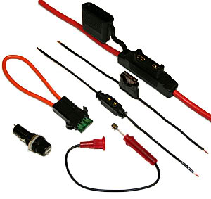
13. In-line fuses
14. Razor Blade
15. 0.5A and 1A fuses
Tips/Process:
1. Car Chassis is the ground
2. Every Black/White wire in the car is ground
3. Start by looking around the area where you want to install your LEDs for any non black/white wires
4. Using a multimeter, connect one lead to the unpainted surface or a bolt with an alligator clip
5. Trace the wire to a plug or to what it is powering because there you will be able to find exposed leads. Otherwise use a blade to scrape a little insulation off.
6. Decide what you’re looking for:
9. Measure the amount of current your light draws using a multimeter
11. Use a fuse that’s 3 – 4 times the current. ( I usually just use 0.5A fuses since superbrightleds have data sheets with current specs.
12. Cut in or merge in the fuse holder with solder
13. The other end of the fuse holder becomes your 12V and anywhere on the Car is your ground!
How to measure current:

Tools:

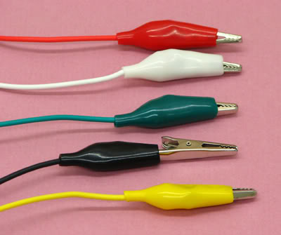
DO NOT USE THESE:

The connection it makes may not be reliable
Tips for finding and hooking up to a 12V source
Equipment:
1. Multimeter
2. Alligator clips
3. Soldering Iron (DO NOT get radioshack brands, buy Weller on eBay)
4. Solder ( The more cancerous it is the easier it is to work with)
5. Helping Hands
6. magnifying glass
7. Crimpers
8. Wire Stripper
9. Crimp on connectors (always put some solder on the joint)
10. Shrink Wrap
11. Electrical tape
12. Heat Gun/Hair Drier
13. In-line fuses
14. Razor Blade
15. 0.5A and 1A fuses
Tips/Process:
1. Car Chassis is the ground
2. Every Black/White wire in the car is ground
3. Start by looking around the area where you want to install your LEDs for any non black/white wires
4. Using a multimeter, connect one lead to the unpainted surface or a bolt with an alligator clip
5. Trace the wire to a plug or to what it is powering because there you will be able to find exposed leads. Otherwise use a blade to scrape a little insulation off.
6. Decide what you’re looking for:
a. Constant 12V (switch is a must)
b. Accessory 12V
c. Ignition 12V
7. Once you found 12V do the following to ensure that 12V is dependent only on what you want it to be.b. Accessory 12V
c. Ignition 12V
a. Open and close the doors
b. Turn the key to Accessory/Ignition/Off
c. Turn on/off all the interior/exterior lights
d. Buckle up – (the line may be a warning LED/Beep for a seatbelt)
8. ALWAYS ALWAYS ALSWAY use an In-line fuse. The fuse has to be rated for at least 12V. What’s most important is the Amperage at which it blows.b. Turn the key to Accessory/Ignition/Off
c. Turn on/off all the interior/exterior lights
d. Buckle up – (the line may be a warning LED/Beep for a seatbelt)
9. Measure the amount of current your light draws using a multimeter
a. Connect one lead of a multimeter to 12V source.
b. Connect the other lead to the positive end of the LED
c. Connect the negative/ground of the LED anywhere to the chassis
10. The multimeter will read the current drawn.b. Connect the other lead to the positive end of the LED
c. Connect the negative/ground of the LED anywhere to the chassis
11. Use a fuse that’s 3 – 4 times the current. ( I usually just use 0.5A fuses since superbrightleds have data sheets with current specs.
12. Cut in or merge in the fuse holder with solder
13. The other end of the fuse holder becomes your 12V and anywhere on the Car is your ground!
How to measure current:
Tools:
DO NOT USE THESE:
The connection it makes may not be reliable
Thread Starter
Senior Member
SL Member
Joined: Mar 2011
Posts: 2,102
From: Nashua, NH
Stuff I no longer need plus I'm moving in 3 days so rather than throwing this out I'll give this for free
Just pay shipping and handling (Paypal obvi)
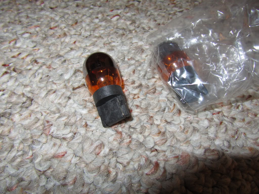
Chrome tipped turn signals

Scion Frames

Toyota logo

Just pay shipping and handling (Paypal obvi)
Chrome tipped turn signals
Scion Frames
Toyota logo


Senior Member
SL Member
Joined: Jul 2008
Posts: 440
From: Needham, MA
Yuriy, will you hang onto those bulbs for me and give them to me next time we meet up on tuesday. i wont be at the next tuesday meet but you can give them to ted and he will give them to me next time i see him
puurrrtttyyyy please?
puurrrtttyyyy please?

SUMBISH@!! Now that I've already decided on my backup camera and it has to be a black plate frame to make it look less obvious... NOW the hot chrome plates are out there! lulz
Someone get these and slip the man a $20 in a return envelope. OR just send him a grab-bag of LEDs.
Someone get these and slip the man a $20 in a return envelope. OR just send him a grab-bag of LEDs.
Thread Starter
Senior Member
SL Member
Joined: Mar 2011
Posts: 2,102
From: Nashua, NH
Dude, too much talking lol. They're yours
Thread Starter
Senior Member
SL Member
Joined: Mar 2011
Posts: 2,102
From: Nashua, NH
Glove Box LED Light DIY#5
You will need:
1. LED:
http://www.superbrightleds.com/cgi-b...FLS.htm#photos
WFLS-B30, using just 3 of them
2. Level Switch:
http://www.radioshack.com/product/in...ductId=2049719
the outside pins are NORMALLY CLOSED CIRCUIT so in this position both wires would pass electricity

3. In-line Fuse Holder:
http://www.radioshack.com/product/in...ductId=2102786
4. 0.5-1A Fuse
Step 1:
Pull off the stereo panel and disconnect the power plug from the clock
Remove the glove box by pushing IN from both sides.
Remove the black covering
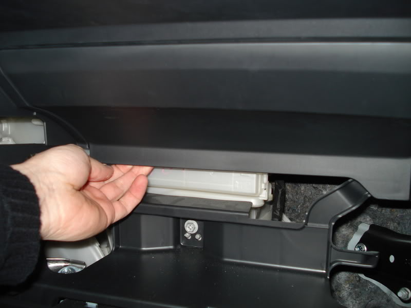

(thanx 1stone! )
)
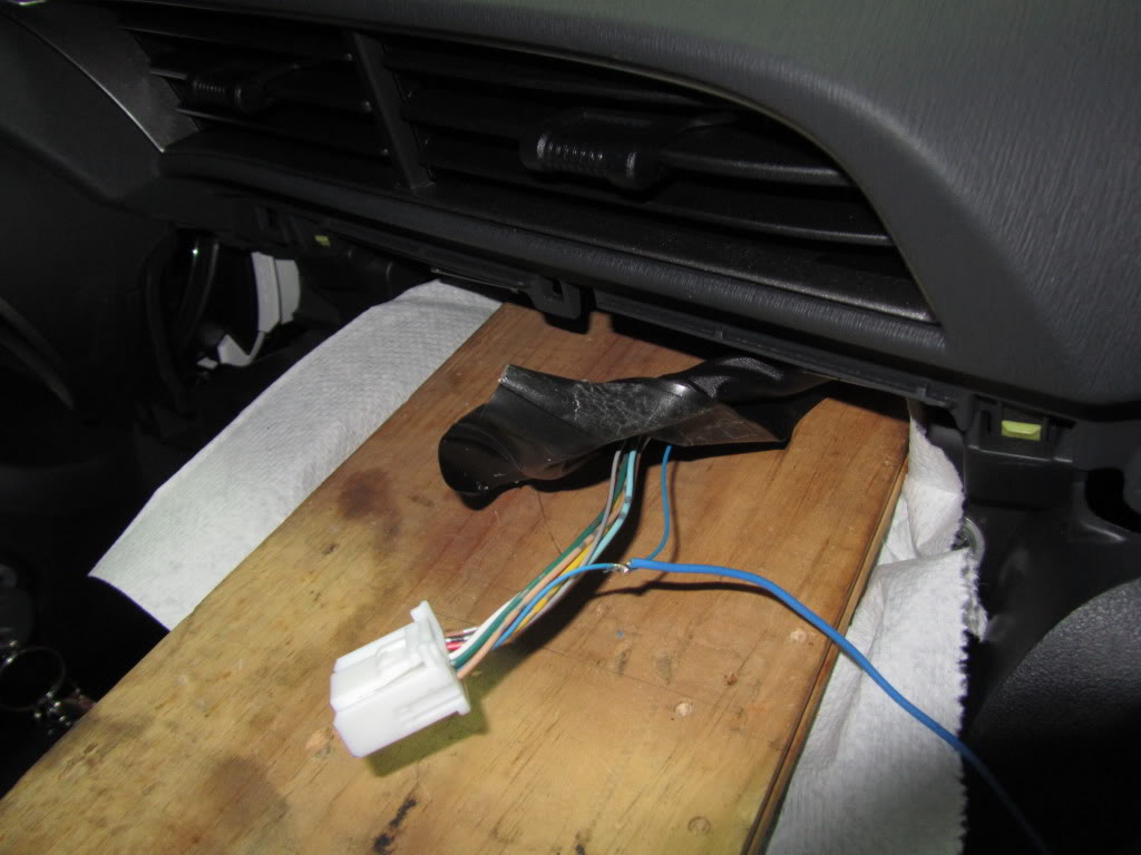
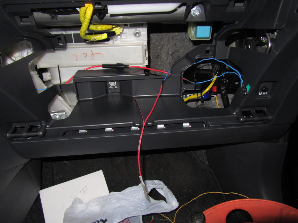
Step 2:
Remove the electric tape and open up the sleeve the power plug is in
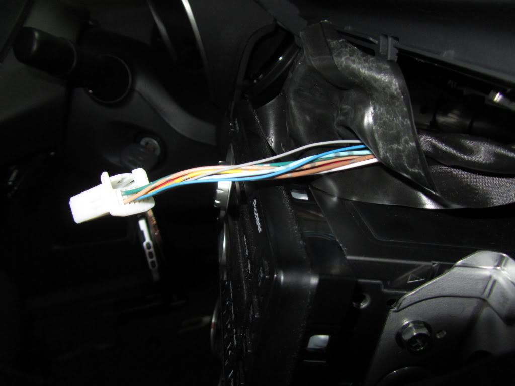
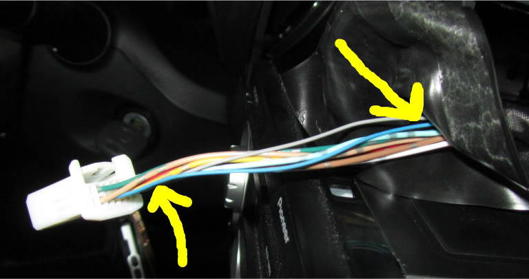
Step 3:
I found that the blue wire is connected to Accessory. You can try looking for constant 12V if you want. I did this out of safety - in case the switch breaks off or whatever else and the light would be ON inside without you ever knowing. Also I dont know what this is conected to so you must use a fuse, maybe this is connected to airbags who knows...
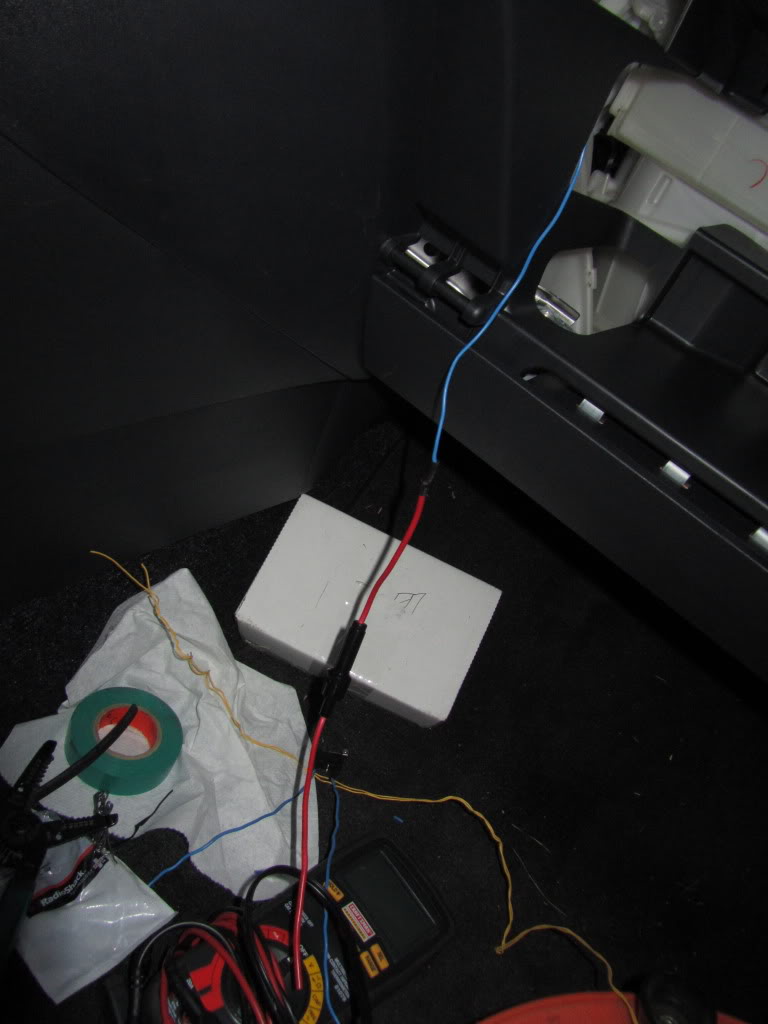
Step 4:
Scrape off some insulation or cut the wire. Solder on a wire.
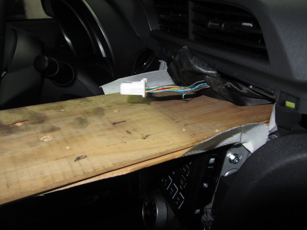
Step 5:
Feed the wire through the back of the stereo into the glove compartment and solder on the in-line fuse

Step 6:
Solder on the wires on the outside pins of the switch and solder one side to the inline fuse holder
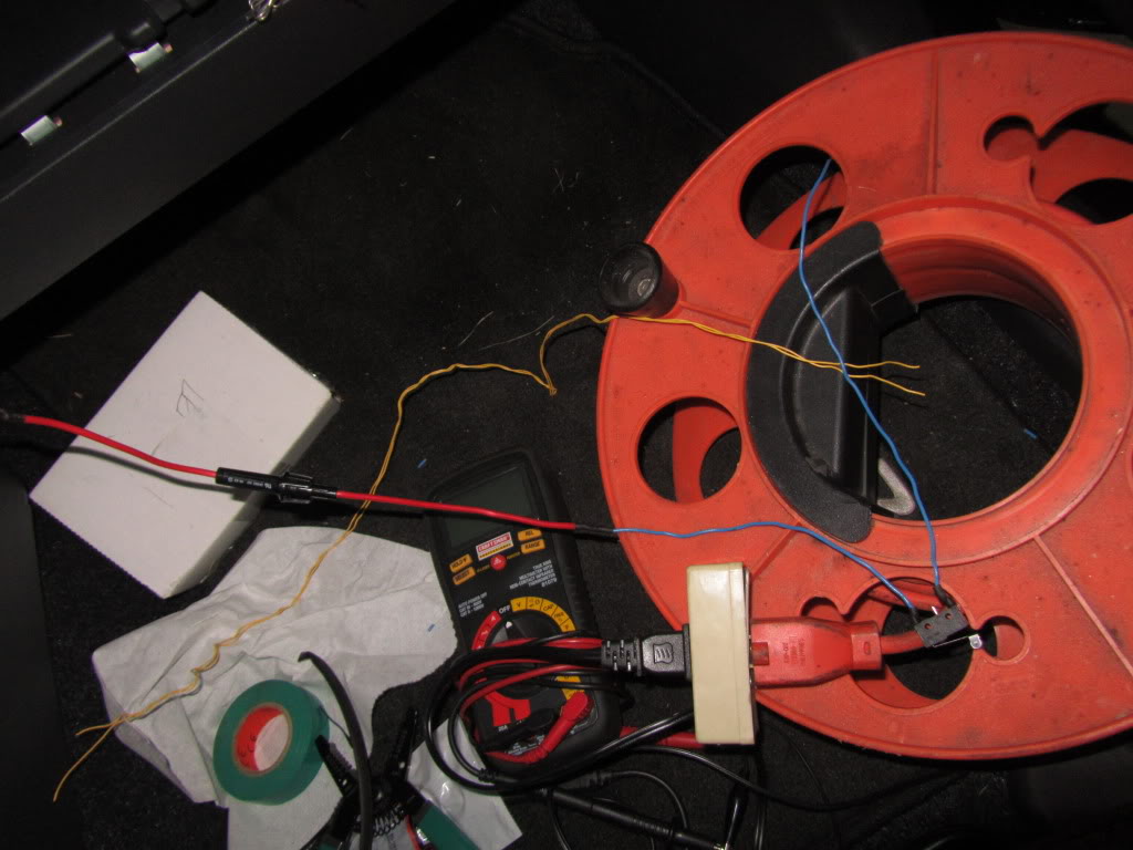
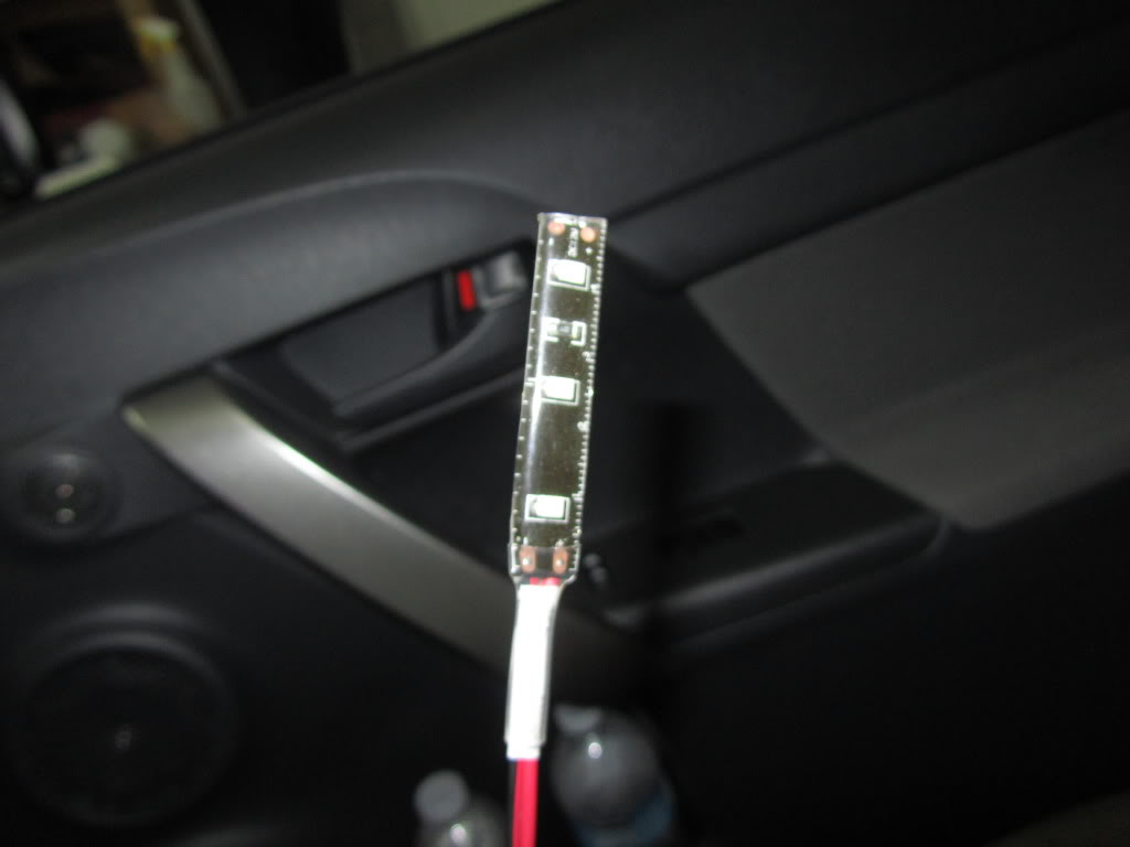
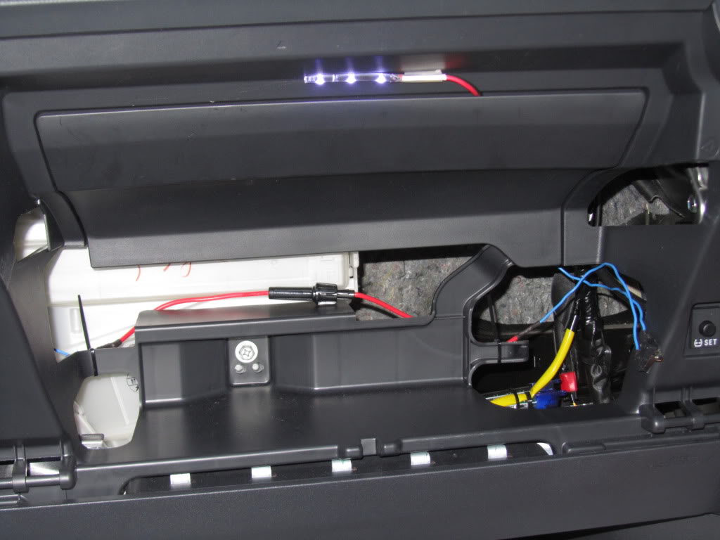
Step 7:
Align everything inside of the glove box compartment
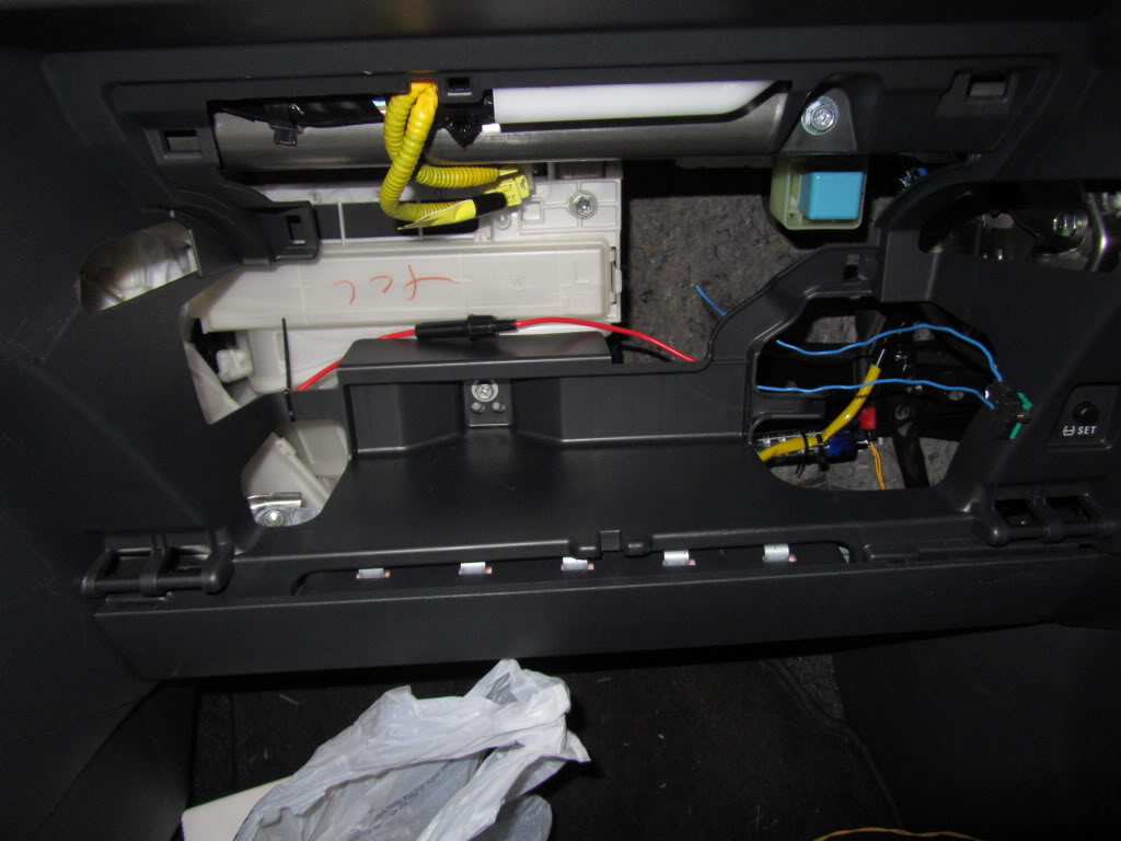
Step 8:
Solder Positive side of the LED to the switch
Step 9:
Ground and mount the LED

Step 10:
Zip tie some wires and re-install the black cover. Turn on the Accessory
Step 11:
Aligning the switch is a bit tricky and will take a couple tries. I just used electrical tape to place it at the edge in the corner then re installed the glove box and tried closing it and listened for a CLICK indicating the the switch broke circuit. Once I found the perfect position I used 3M double sided heavy duty tape. I will secure it better in the future but for now it holds up EXTREMELY PROMISING

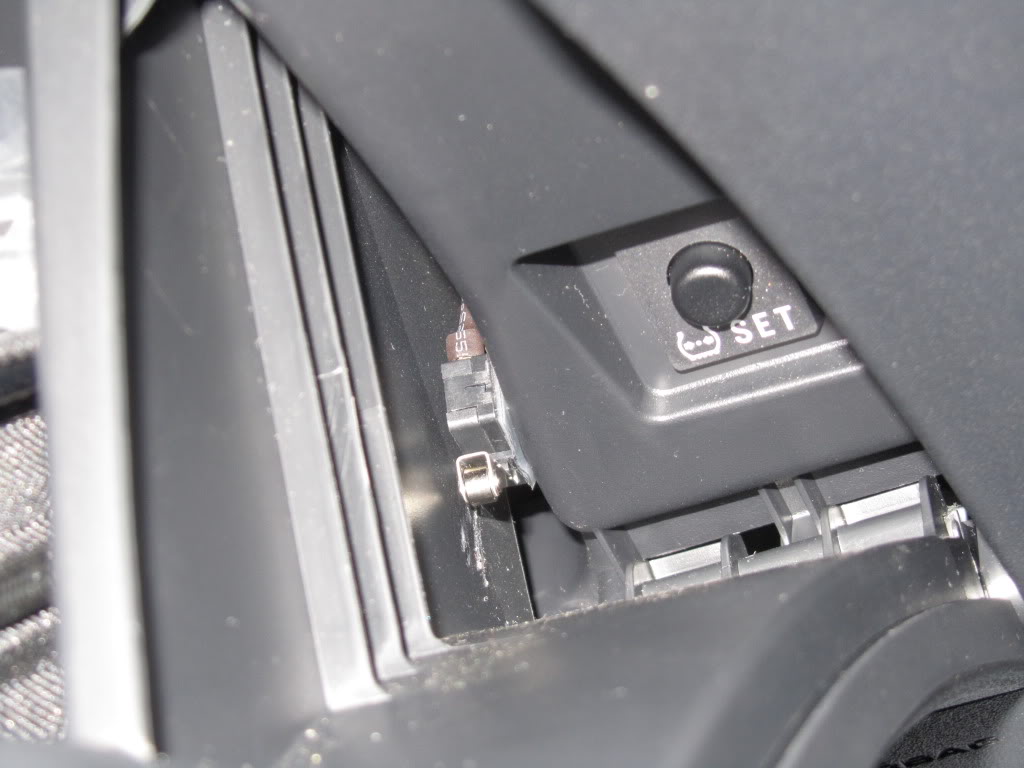
You're Done!
You will need:
1. LED:
http://www.superbrightleds.com/cgi-b...FLS.htm#photos
WFLS-B30, using just 3 of them
2. Level Switch:
http://www.radioshack.com/product/in...ductId=2049719
the outside pins are NORMALLY CLOSED CIRCUIT so in this position both wires would pass electricity
3. In-line Fuse Holder:
http://www.radioshack.com/product/in...ductId=2102786
4. 0.5-1A Fuse
Step 1:
Pull off the stereo panel and disconnect the power plug from the clock
Remove the glove box by pushing IN from both sides.
Remove the black covering
(thanx 1stone!
Step 2:
Remove the electric tape and open up the sleeve the power plug is in
Step 3:
I found that the blue wire is connected to Accessory. You can try looking for constant 12V if you want. I did this out of safety - in case the switch breaks off or whatever else and the light would be ON inside without you ever knowing. Also I dont know what this is conected to so you must use a fuse, maybe this is connected to airbags
Step 4:
Scrape off some insulation or cut the wire. Solder on a wire.
Step 5:
Feed the wire through the back of the stereo into the glove compartment and solder on the in-line fuse
Step 6:
Solder on the wires on the outside pins of the switch and solder one side to the inline fuse holder
Step 7:
Align everything inside of the glove box compartment
Step 8:
Solder Positive side of the LED to the switch
Step 9:
Ground and mount the LED
Step 10:
Zip tie some wires and re-install the black cover. Turn on the Accessory
Step 11:
Aligning the switch is a bit tricky and will take a couple tries. I just used electrical tape to place it at the edge in the corner then re installed the glove box and tried closing it and listened for a CLICK indicating the the switch broke circuit. Once I found the perfect position I used 3M double sided heavy duty tape. I will secure it better in the future but for now it holds up EXTREMELY PROMISING
You're Done!

DaYUUM/Scion Evolution
SL Member
Joined: Jan 2011
Posts: 3,538
From: Southern California
damnit! i overslept on the release...hahaha but still the first in line to comment!
that is a great write up! I will be putting that on my list. thank you oh great LEDMaster Blade
that is a great write up! I will be putting that on my list. thank you oh great LEDMaster Blade
Thread Starter
Senior Member
SL Member
Joined: Mar 2011
Posts: 2,102
From: Nashua, NH
AC Line Insulation explained
 HUH/WHY?:
Car manufacturers place the AC lines not where they should be but rather try to find the shortest way. As a result, they run way too close to the engine and the efficiency of the AC is decreased.
Stuff I used:
Armacell Armaflex 1/2 in. x 6 ft. Rubber Self-Seal Pipe Wrap Insulation - $5
http://www.homedepot.com/Plumbing-Pi...atalogId=10053
Armacell Armaflex 3/4 in. x 6 ft. Rubber Self-Seal Pipe Wrap Insulation - $6
http://www.homedepot.com/Plumbing-Pi...atalogId=10053
You will need only a couple feet total
Also
Heatshield CFT Cool Foil Tape - any kind
==========================================================================
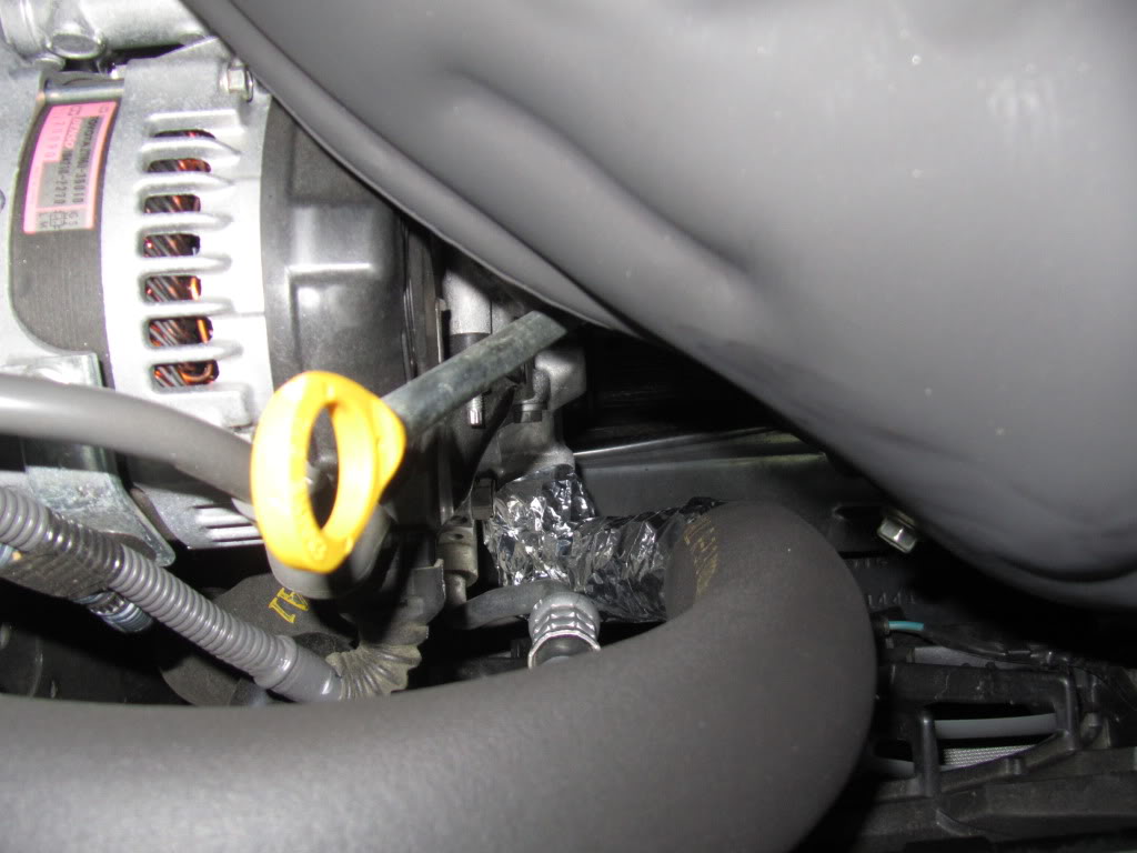
All you do is wrap one line that brings the cold air into the car.
If you want even more insulation then apply the aluminum tape on top of it
On my car the aluminum was only applied down by the exhaust manifold since you cant see it and the line is really close to it
Result:
The AC performance is definitely increased!
Before I'd run the AC on full and it would be just comfortable
Now I find myself shivering when it's on 4 or 3 so I can turn it down, which saves energy and cuts down on noise


Car manufacturers place the AC lines not where they should be but rather try to find the shortest way. As a result, they run way too close to the engine and the efficiency of the AC is decreased.
Stuff I used:
Armacell Armaflex 1/2 in. x 6 ft. Rubber Self-Seal Pipe Wrap Insulation - $5
http://www.homedepot.com/Plumbing-Pi...atalogId=10053
Armacell Armaflex 3/4 in. x 6 ft. Rubber Self-Seal Pipe Wrap Insulation - $6
http://www.homedepot.com/Plumbing-Pi...atalogId=10053
You will need only a couple feet total
Also
Heatshield CFT Cool Foil Tape - any kind
==========================================================================
All you do is wrap one line that brings the cold air into the car.
If you want even more insulation then apply the aluminum tape on top of it
On my car the aluminum was only applied down by the exhaust manifold since you cant see it and the line is really close to it
Result:
The AC performance is definitely increased!
Before I'd run the AC on full and it would be just comfortable
Now I find myself shivering when it's on 4 or 3 so I can turn it down, which saves energy and cuts down on noise

Thread Starter
Senior Member
SL Member
Joined: Mar 2011
Posts: 2,102
From: Nashua, NH
yeah def, if you wrap the whole thing in aluminum foil then it will be even better!
but will look like ____
not much to DIY, just get 2 sizes of insulation for the metal lines and rubber ones(rubber lines are a bit thicker)
then measure and cut
DIY done!

Thread Starter
Senior Member
SL Member
Joined: Mar 2011
Posts: 2,102
From: Nashua, NH
I know the economy is real ____ty nowadays but in that case you could use a cheaper insulation made by the same company
http://www.homedepot.com/Armacell/h_...atalogId=10053
it only costs $1.64
http://www.homedepot.com/Armacell/h_...atalogId=10053
it only costs $1.64

Member
SL Member
Joined: Jun 2011
Posts: 78
so I had a hard time trying to locate the wire to the dome lights (any wire that works when the doors are opened) and try to tap in some leds. Do you happen to know and take a picture of where one is located? I've been looking under the driver side dash and that driver side panel cluttered with different plugs...
haha sorry I'm pretty noob at this.
haha sorry I'm pretty noob at this.

Senior Member
SL Member
Joined: Feb 2011
Posts: 1,018
From: Dallas/Houston, TX
i have all my leds wired to the rear dome. just put the wire and twisted it around the metal in the dome housing. then all the others are tapped into that wire. pretty easy and i really didnt know what i was doing lol
Thread Starter
Senior Member
SL Member
Joined: Mar 2011
Posts: 2,102
From: Nashua, NH
I was gonna look into the front dome and see how easy it is to tap into it.
I tried looking under the dash for door switch plug but it's OVERLY CROWDED
It's full of wiring and fuses from the alarm/rem start/tilt sensor/one touch windows/remote windows/few leds
SOOOOOOOOOOOOO it's a MESS