


Light on Door Open OR Switch


Thread Starter
Member
Joined: Sep 2007
Posts: 31
 Light on Door Open OR Switch
I am adding some LED accents to my car - under dash, etc - and I want them to operate when the doors open OR when a switch is flipped.
I know where to pickup the door open trigger from another thread - so I know how to make the lights go on when the door opens.
I know how to make the lights go on with a switch.
What I can't figure out is how to do either/or. I want them to *always* go on with the door (then turn off when the door is closed). Then when the door is closed I'd like to be able to flip a switch and turn them on.
Anyone care to draw up a wiring diagram (however simple it is)?
ThankS!!!
I know where to pickup the door open trigger from another thread - so I know how to make the lights go on when the door opens.
I know how to make the lights go on with a switch.
What I can't figure out is how to do either/or. I want them to *always* go on with the door (then turn off when the door is closed). Then when the door is closed I'd like to be able to flip a switch and turn them on.
Anyone care to draw up a wiring diagram (however simple it is)?
ThankS!!!

Senior Member


SoCal tC Club
SL Member
Team N.V.S.
Scinergy
Scion Evolution
Joined: Oct 2004
Posts: 15,699
wire another ground thru the switch...
so when you flip it.. it goes to ground... thus lighting it up.
it's pretty much identical to the dome light circuit.... you have the switch to 'DOOR', the light turns on with the door... you turn that switch to 'ON'.. well... it turns on..
so when you flip it.. it goes to ground... thus lighting it up.
it's pretty much identical to the dome light circuit.... you have the switch to 'DOOR', the light turns on with the door... you turn that switch to 'ON'.. well... it turns on..
Thread Starter
Member
Joined: Sep 2007
Posts: 31
Originally Posted by SquallLHeart
wire another ground thru the switch...
so when you flip it.. it goes to ground... thus lighting it up.
it's pretty much identical to the dome light circuit.... you have the switch to 'DOOR', the light turns on with the door... you turn that switch to 'ON'.. well... it turns on..
so when you flip it.. it goes to ground... thus lighting it up.
it's pretty much identical to the dome light circuit.... you have the switch to 'DOOR', the light turns on with the door... you turn that switch to 'ON'.. well... it turns on..
In this picture, from the Puddle Lamp thread, it shows the connections for Door Sill light-up:

So in the case of a single light (to simplify the thought) I can connect the negative and positive indicated in this picture to either side of my light.
In the case of a switched, I can grab a positive -> switch -> light and then grab a negative to the other side of the light (or vice-versa).
Now it sounds like you are saying for me to do:
- positive from door sill pic to the light
- negative from the door sill pic to the light
- another negative to a switch to a light
So there are 2 separate negative lines running to the same side of the light.
Is this correct? And if so is there another negative in that door sill pic that's not door switched (to keep everything "together" and clean)?
If this isn't correct can you advise?
THANKS for the quick response!
Thanks

Senior Member
Team Hamster
SL Member
Team ScioNRG
Joined: Dec 2006
Posts: 898
From: Burlington, MA
I actually have the same thing for mine, except I have it wired into the dome light rather than a direct door open trigger. I have an On-Off-On switch from a local store, that the first On is to the domes and the second is to a 12v source.
I'm bad at drawing diagrams quickly (as you can see), but the back of the switch has 3 prongs where I put all my negative wires. The middle one is from the LED negative (-). One side is grounded to the frame, and the other is tapped into the negative wire for the dome (in your case the door trigger). The positive (+) wire from the LED is given a constant 12v source. You're toggling between two different circuits.
It works for me, so I don't see why it wouldn't work for you. Good luck!
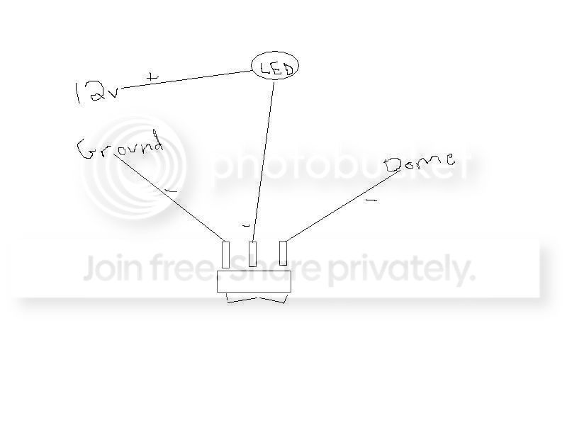
I'm bad at drawing diagrams quickly (as you can see), but the back of the switch has 3 prongs where I put all my negative wires. The middle one is from the LED negative (-). One side is grounded to the frame, and the other is tapped into the negative wire for the dome (in your case the door trigger). The positive (+) wire from the LED is given a constant 12v source. You're toggling between two different circuits.
It works for me, so I don't see why it wouldn't work for you. Good luck!
Senior Member
SoCal tC Club
SL Member
Team N.V.S.
Scinergy
Scion Evolution
Joined: Oct 2004
Posts: 15,699
yes.. have two lines from the negative side from the light
one that goes to that blue wire that goes to gnd when the door opens.
and another one thru a switch that goes to gnd that's anywhere in the car... the chassis itself is a ground.. so any convenient nut or bolt you can find.
one that goes to that blue wire that goes to gnd when the door opens.
and another one thru a switch that goes to gnd that's anywhere in the car... the chassis itself is a ground.. so any convenient nut or bolt you can find.
Thread Starter
Member
Joined: Sep 2007
Posts: 31
Originally Posted by SquallLHeart
yes.. have two lines from the negative side from the light
one that goes to that blue wire that goes to gnd when the door opens.
and another one thru a switch that goes to gnd that's anywhere in the car... the chassis itself is a ground.. so any convenient nut or bolt you can find.
one that goes to that blue wire that goes to gnd when the door opens.
and another one thru a switch that goes to gnd that's anywhere in the car... the chassis itself is a ground.. so any convenient nut or bolt you can find.
Blue -> Light (Negative)
Red -> Light (Positive)
Some Screw (Ground) -> Switch -> Light (Negative)
By doing this I will get the lights when:
- Switch OFF, Door OPEN
- Switch ON, Door CLOSED
I assume nothing "bad" will happen with the Switch ON, Door OPEN.
THANKS!
Thread Starter
Member
Joined: Sep 2007
Posts: 31
OK - final question - what if I have 2 lights that I want to switch separately but still have turn on with the door? Will this work:
Blue -> Light 1 (Negative)
Blue -> Light 2 (Negative)
Red -> Light 1 (Positive)
Red -> Light 2 (Positive)
Some Screw (Ground) -> Switch 1 -> Light 1 (Negative)
Some Screw (Ground) -> Switch 2 -> Light 2 (Negative)
Or will the switches operate both together since at the end of the day they are all tied to the Red and Blue? Or am I being dense?
Blue -> Light 1 (Negative)
Blue -> Light 2 (Negative)
Red -> Light 1 (Positive)
Red -> Light 2 (Positive)
Some Screw (Ground) -> Switch 1 -> Light 1 (Negative)
Some Screw (Ground) -> Switch 2 -> Light 2 (Negative)
Or will the switches operate both together since at the end of the day they are all tied to the Red and Blue? Or am I being dense?
Thread Starter
Member
Joined: Sep 2007
Posts: 31
Originally Posted by SquallLHeart
nope.. the light should already be on.
Now would what I put a couple posts back work for 2 lights/switches or would I need something else (a relay perhaps) thrown in there?
So how would I get 2 circuits to operate in the manner described:
- Both on when door open
- Circuit 1 on when Switch 1 on
- Citcuit 2 on when Switch 2 on
- Both on when both switches on
Senior Member
SoCal tC Club
SL Member
Team N.V.S.
Scinergy
Scion Evolution
Joined: Oct 2004
Posts: 15,699
just use two separate switches
and that answer was meant for
nothing bad will happen.
and that answer was meant for
Originally Posted by ungarod
I assume nothing "bad" will happen with the Switch ON, Door OPEN.
Thread Starter
Member
Joined: Sep 2007
Posts: 31
Originally Posted by SquallLHeart
just use two separate switches
Blue -> Light 1 (Negative)
Blue -> Light 2 (Negative)
Red -> Light 1 (Positive)
Red -> Light 2 (Positive)
Some Screw (Ground) -> Switch 1 -> Light 1 (Negative)
Some Screw (Ground) -> Switch 2 -> Light 2 (Negative)

Thread Starter
Member
Joined: Sep 2007
Posts: 31
Originally Posted by ungarod
Originally Posted by SquallLHeart
just use two separate switches
Blue -> Light 1 (Negative)
Blue -> Light 2 (Negative)
Red -> Light 1 (Positive)
Red -> Light 2 (Positive)
Some Screw (Ground) -> Switch 1 -> Light 1 (Negative)
Some Screw (Ground) -> Switch 2 -> Light 2 (Negative)
Situation - Door Closed, Switch 2 ON
Positive -> Light 2 ON/CONNECTED
Ground -> Switch 2 -> Light 2 ON/CONNECTED
Circuit is complete - light goes on
But doesn't also:
Light 2 -> Blue get ON/CONNECTED
And this is in turn connected to Light 1?
And since the Blue is connected to Negative on the light, and the negative of light 2 is connected to GROUND now, wouldn't that also connect Light 1 to GROUND?
Thread Starter
Member
Joined: Sep 2007
Posts: 31
I am definately thinking this isn't as simple as 2 switches - I need a relay - here's why - the negative on both lights are connected to 2 places - both go to the door ground terminal and each go to a switch. But by connecting them to the door ground they are essentially connected together - so flipping a switch (either) will connect the negatives (both) to ground.
I think I need a relay that disconnects the link between the 2 light negatives (the ones that tie to the door ground) that is open when the door is closed.
I think I need a relay that disconnects the link between the 2 light negatives (the ones that tie to the door ground) that is open when the door is closed.
Senior Member
Team Hamster
SL Member
Team ScioNRG
Joined: Dec 2006
Posts: 898
From: Burlington, MA
Not sure if you noticed my post of the first page, but you can get an On-Off-On switch that can handle both grounds. I drew the diagram quickly and might not have explained it well enough, but look it over and see what you think. Ask questions if its not clear enough.
Otherwise you might have to use a relay of some sort.
Otherwise you might have to use a relay of some sort.

Senior Member
Team Hamster
SL Member
Team ScioNRG
Joined: Dec 2006
Posts: 898
From: Burlington, MA
Clearly I'm not the "smart" person you're looking for. 
All I can tell you (from first hand experience) is that once the doors close the negative dome light wire (the blue wire you speak of) will be inactive. If you want the lights to turn on when the doors are closed, you could do it my way or put a switch on a wire to the ground and turn it on allowing your circuit to be complete. You can hook multiple switches onto wires that all connect to the same ground, and it won't turn on the wrong light as long as the other switch is off.
Don't know if that helps but I've tried.
All I can tell you (from first hand experience) is that once the doors close the negative dome light wire (the blue wire you speak of) will be inactive. If you want the lights to turn on when the doors are closed, you could do it my way or put a switch on a wire to the ground and turn it on allowing your circuit to be complete. You can hook multiple switches onto wires that all connect to the same ground, and it won't turn on the wrong light as long as the other switch is off.
Don't know if that helps but I've tried.
Thread Starter
Member
Joined: Sep 2007
Posts: 31
Originally Posted by powerofSHN
Clearly I'm not the "smart" person you're looking for.
All I can tell you (from first hand experience) is that once the doors close the negative dome light wire (the blue wire you speak of) will be inactive. If you want the lights to turn on when the doors are closed, you could do it my way or put a switch on a wire to the ground and turn it on allowing your circuit to be complete. You can hook multiple switches onto wires that all connect to the same ground, and it won't turn on the wrong light as long as the other switch is off.
Don't know if that helps but I've tried.
All I can tell you (from first hand experience) is that once the doors close the negative dome light wire (the blue wire you speak of) will be inactive. If you want the lights to turn on when the doors are closed, you could do it my way or put a switch on a wire to the ground and turn it on allowing your circuit to be complete. You can hook multiple switches onto wires that all connect to the same ground, and it won't turn on the wrong light as long as the other switch is off.
Don't know if that helps but I've tried.

Senior Member
SL Member
Joined: Oct 2006
Posts: 1,666
From: Lake Elsinore, CA
will this also end up turning the dome lights on? Cause you will be completing the ground circuit with the ground switch that you have. Im thinking it will turn on the domes when the door is closed and the switch is on...

