


CCFL to door circuit question


Thread Starter
Junior Member


SL Member
Joined: Dec 2005
Posts: 20
 CCFL to door circuit question
I'm installing my CCFLs for a dome light, and like a good engineer, I'm isolating the power to the CCFLs through a relay. This works, but when the doom light goes into the dimming-to-off cycle, the relay buzzes pretty loudly.  (Didn't expect that!) Apparently the dimming is accomplished via pulsing the power instead of a steady voltage change.
So now I'm looking for ideas on how to stop the relay from buzzing when the light is suppose to dim. (I'd rather have the CCFLs just go off at some point rather than dealing with the whole dimming issue.) I've tried putting a capacitor across the relay coil lines, but that did nothing. Anyone got any inexpensive suggestions?
(Didn't expect that!) Apparently the dimming is accomplished via pulsing the power instead of a steady voltage change.So now I'm looking for ideas on how to stop the relay from buzzing when the light is suppose to dim. (I'd rather have the CCFLs just go off at some point rather than dealing with the whole dimming issue.) I've tried putting a capacitor across the relay coil lines, but that did nothing. Anyone got any inexpensive suggestions?

Admin Emeritus


SL Member
Joined: Jan 2005
Posts: 14,570
From: University Place, WA
My only suggestion would be to bypass the dimming circuit (in the door lock control unit) by moving your relay control feed to the input side of the controller rather than the output.
(I'd probably try to isolate your two pickoffs from the input side with diodes so the lock controller doesn't get confused into thinking your doors are always open.)
Here's the schematic for the OEM circuit...
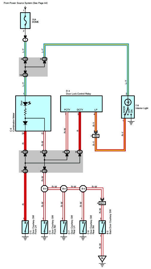
(I found it interesting that the dimming is possibly PWM of the ground to the dome light, from what you say.)
Good luck!
(I'd probably try to isolate your two pickoffs from the input side with diodes so the lock controller doesn't get confused into thinking your doors are always open.)
Here's the schematic for the OEM circuit...
(I found it interesting that the dimming is possibly PWM of the ground to the dome light, from what you say.)
Good luck!


Thread Starter
Junior Member
SL Member
Joined: Dec 2005
Posts: 20
Thanks...
Oh just lovely. Getting to that is such joy...I can duck under the driver's dashboard and reach up to D4, but finding the right 2 lines and tapping into them will prove...challenging, unless I take apart the entire dash!
Do you think I can get to C6 (Combination Meter) if I take apart the instrument cluster? If I can, then tapping into those lines there might be easier.
Also, if I read this schematic correctly, it appears that those two lines float when all doors are closed, and ground when one is open...correct?
Admin Emeritus
SL Member
Joined: Jan 2005
Posts: 14,570
From: University Place, WA
The combo meter connector would probably be easier to get to than D4. Hopefully you can dig out the proper leads there.
In any case, if you can get to those leads before the controller modifies the signal, it would probably be a lot better.
One more pic...

(The signal does seem to be ground/door open, float/door closed.)
As I said: Good luck!
In any case, if you can get to those leads before the controller modifies the signal, it would probably be a lot better.
One more pic...
(The signal does seem to be ground/door open, float/door closed.)
As I said: Good luck!
Thread Starter
Junior Member
SL Member
Joined: Dec 2005
Posts: 20
Easier than I thought!
Just in case anyone is interested and watching this thread...
I found out that if I take the instrument cluster out (don't have to disconnect it, just unscrew it and move it aside), the Door Lock Control Relay (D4) is directly under the speedometer! And it's fairly trivial to reach in and pull the connector off to get to the wires there.
And as a bonus, I discovered that I only need to tap into one of those input wires. Here's the scoop:
The DCTY (pin 5 on D4) will ground only when the driver's door is open. However, the PCTY (pin 7 on D4) will ground whenever any door is open (including the driver's door). Pretty smart, eh? So since I want my cool new CCFLs to light up when any door is open, I only need to connect into PCTY.
Tomas:
Since I only need to tap into one line, and I'm planning on using that line as the ground for a relay's coil, do you think I still need a diode? (I'm thinking I don't, but it's always good to get a second opinion.)
I found out that if I take the instrument cluster out (don't have to disconnect it, just unscrew it and move it aside), the Door Lock Control Relay (D4) is directly under the speedometer! And it's fairly trivial to reach in and pull the connector off to get to the wires there.
And as a bonus, I discovered that I only need to tap into one of those input wires. Here's the scoop:
The DCTY (pin 5 on D4) will ground only when the driver's door is open. However, the PCTY (pin 7 on D4) will ground whenever any door is open (including the driver's door). Pretty smart, eh? So since I want my cool new CCFLs to light up when any door is open, I only need to connect into PCTY.
Tomas:
Since I only need to tap into one line, and I'm planning on using that line as the ground for a relay's coil, do you think I still need a diode? (I'm thinking I don't, but it's always good to get a second opinion.)


Thread
Thread Starter
Forum
Replies
Last Post
bootlgr
Scion xA/xB 1st-Gen ICE & Interior
1
Jan 26, 2016 01:22 AM
