


HELP!!! shorted out dome light control?


Thread Starter
Senior Member


SL Member
Joined: Aug 2005
Posts: 309
From: Louisville, KY

I pulled the door lock control relay out and took it apart. i can't find any burnt up pieces on the board. i also found out that the part is specific to a scion XB not on any other scions or toyotas.

Member
SL Member
Joined: Aug 2004
Posts: 77
From: Atlanta, GA
Re: dome light
Originally Posted by Jan06xB
Hey where is that relay for the dome light - I want to tap into it for my alarm system. Seems each door button is a separate signal to it so the alarm can't be triggered by any of the four doors being opened since there is only one door input to the alarm and 4 doors plus the trunk signal wire is also an alarm input which also goes to the same relay timer.

Senior Member
SL Member
Joined: Feb 2006
Posts: 1,971
From: Tiverton, RI
dome light switches
Thanks Invisible21 - the thing that threw me was the two door buttons that I checked were the driver and passenger doors which now I see that the driver door is wired separate from the others duh! SO I didn't think I could trigger off the door and I wanted to try to trigger the rear hatch separate. Also the wiring from each door switch went into the harness and was really hard to trace without knowing where they end up under the dash or in the engine bay - now I know - Thanks!
Senior Member
SL Member
Joined: Feb 2006
Posts: 1,971
From: Tiverton, RI
dome light
Originally Posted by KYfirefighter
I pulled the door lock control relay out and took it apart. i can't find any burnt up pieces on the board. i also found out that the part is specific to a scion XB not on any other scions or toyotas.
Thread Starter
Senior Member
SL Member
Joined: Aug 2005
Posts: 309
From: Louisville, KY
Thanks for the help i took some pictures i will upload them later. also i need to know which terminal on the door lock control relay is the one for the nagative out to the domelight i have seen thomas post i diagram with the pin numbers for the connection but not a discription of each pin.

Admin Emeritus

SL Member
Joined: Jan 2005
Posts: 14,570
From: University Place, WA
The numbers on the schematic refer to the connector and pin number, the pics of the connectors show the connector and pin numbers...
Both are shown in the link above (https://www.scionlife.com/forums/viewtopic.php?t=107795) and are discussed in that topic.
The pics of the controller's gizzard should be interesting.
Both are shown in the link above (https://www.scionlife.com/forums/viewtopic.php?t=107795) and are discussed in that topic.
The pics of the controller's gizzard should be interesting.
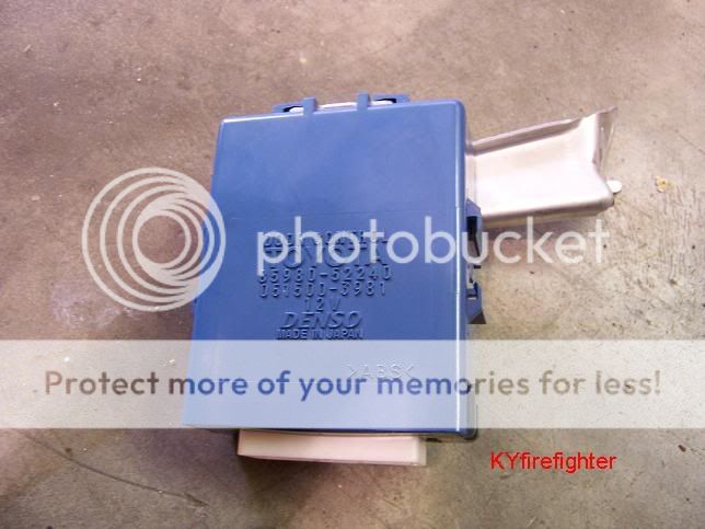
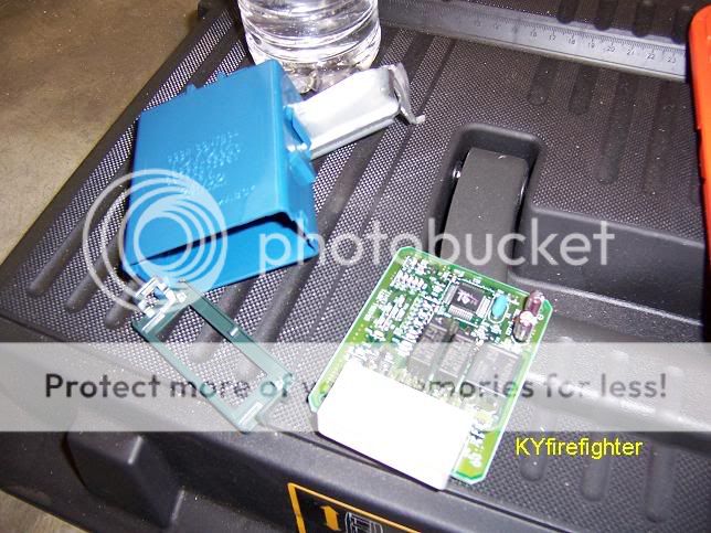
Admin Emeritus
SL Member
Joined: Jan 2005
Posts: 14,570
From: University Place, WA
Hmmmmmmm... Complex littled beast, eh? Lots of tiny, tiny parts that wouldn't like 12V at 15A or more zapped across 'em.
If possible a macro shot of both sides of the board - straight on - would be fantastic.
Thanks for the pics so far! :D
If possible a macro shot of both sides of the board - straight on - would be fantastic.
Thanks for the pics so far! :D
Senior Member
SL Member
Joined: Feb 2006
Posts: 1,971
From: Tiverton, RI
YEAH full frame shot would help - looks like it will probably be a surface mounted transistor and the IC with all the leads is probably a micro controller. Amazing how complicated the stuff is when it doesn't need to be. I actually pulled off the bezel around my speedo today and saw the big blue box - yikes that a lot of stuff to lock some doors and turn on a light. My Geo would at least lock the front doors at 8mph automatically - sort of miss that. And an easier to reach door lock unlock button like right above the inside door handle instead of behind my left shoulder.
Thread Starter
Senior Member
SL Member
Joined: Aug 2005
Posts: 309
From: Louisville, KY
Ask and you shall Receive...
I kept the images full size to make them easier to see so I am posting links to images instead of putting the in this forum.
Front
http://i42.photobucket.com/albums/e3...r/100_0334.jpg
Back
http://i42.photobucket.com/albums/e3...r/100_0335.jpg
I tried a bunch of thing to get these shots as clear as possible but I ended up going outside in the sun and setting up my tripod and they came out pretty clear.
I kept the images full size to make them easier to see so I am posting links to images instead of putting the in this forum.
Front
http://i42.photobucket.com/albums/e3...r/100_0334.jpg
Back
http://i42.photobucket.com/albums/e3...r/100_0335.jpg
I tried a bunch of thing to get these shots as clear as possible but I ended up going outside in the sun and setting up my tripod and they came out pretty clear.

Senior Member
SL Member
Joined: Dec 2003
Posts: 1,216
it doesn't look like something is fried. try if you can urge another xB owner to do a swap just to test it. If found really dead, make friend with someone who knows electronic, and probably check eack component starting with that 2 capacitor.
Member
SL Member
Joined: Aug 2004
Posts: 77
From: Atlanta, GA
it's hard to tell...but it looks like D18 on the backside (far right) might be fried...D19 also looks kind of beaten up (backside, near the bottom-center of the board).
These could just be dirty, so I'm not sure...you might want to get a multi-meter and check for continuity. Other than that I don't see any obviously burnt leads or traces.
Looking at it a little more, either or both of those diodes could be the problem bc they're both connected directly the connector (not sure if they're inputs or outputs).
Also, I can't believe they charge $425 for that sucker...I mean it is more complicated than a relay but at the volume they make those, they couldn't cost near that much to manufacture!
These could just be dirty, so I'm not sure...you might want to get a multi-meter and check for continuity. Other than that I don't see any obviously burnt leads or traces.
Looking at it a little more, either or both of those diodes could be the problem bc they're both connected directly the connector (not sure if they're inputs or outputs).
Also, I can't believe they charge $425 for that sucker...I mean it is more complicated than a relay but at the volume they make those, they couldn't cost near that much to manufacture!
Thread Starter
Senior Member
SL Member
Joined: Aug 2005
Posts: 309
From: Louisville, KY
when i looked at the picture it kinda looked that way to me as well but it also liks like it could just be the coating that is in the backside has imperfectons on those two.
Admin Emeritus
SL Member
Joined: Jan 2005
Posts: 14,570
From: University Place, WA
OK, There are two parts that are first to be suspect: One of the tiny relays might have welded it's contacts if the dome light was ON when power hit the ground lead, and the other is the component marked "K2018"...
It looks like the relay applies power to the dome light and the other applies the ground that slowly fades away when the relay opens (dims the light).
Here are some slightly re-worked pics...
http://tijil.org/DLC_bottom.jpg
http://tijil.org/DLC_top.jpg
http://tijil.org/DLC_see_thru.jpg
...with the dome light connector pin and circuit traces highlighted.
Hope that helps.
(Looks like it would be a real PITA to try to replace the relay - if one could even find a replacement.)
As I said before, GOOD LUCK!
{oops - bad code - fixed *sigh*}
It looks like the relay applies power to the dome light and the other applies the ground that slowly fades away when the relay opens (dims the light).
Here are some slightly re-worked pics...
http://tijil.org/DLC_bottom.jpg
http://tijil.org/DLC_top.jpg
http://tijil.org/DLC_see_thru.jpg
...with the dome light connector pin and circuit traces highlighted.
Hope that helps.
(Looks like it would be a real PITA to try to replace the relay - if one could even find a replacement.)
As I said before, GOOD LUCK!
{oops - bad code - fixed *sigh*}
Senior Member
SL Member
Joined: Feb 2006
Posts: 1,971
From: Tiverton, RI
If you have an ohm meter then test the resistance across the suspect diodes on the lowest 1 ohm scale and see if there is low resistance in both directions across the diode. If it is shorted then it is probably bad and keeping the light on. Then the next thing would be to check the transistors T1 and T11 is the big one in the center for shorts to the positive. But you should concentrate on the components that connect to the leads going to the Dome Light and not the door locks which will probably be the higher powered components i.e. T11 as the solenoid in the door locks will take a lot more power than the dome light.


Senior Member
SL Member
Joined: Feb 2006
Posts: 1,971
From: Tiverton, RI
BoughettiXB - did you perhaps swap the wires connecting to your dome light and the LED bulbs don't work because you have the polarity backwards?? LEDs only light up with DC power applied one way where as the regular incandecent bulb doesn't care.