
My First LED Swap Ever! xD... Success at last!

Thread Starter
Senior Member
SL Member
Joined: Jan 2009
Posts: 203
Here goes, I have the parts in from Custom xB Gauges, and Garage 1217... I have the gauge and clock out and taken apart. Now for the soldering of many teensy little lights! I'll post pictures as I progress:
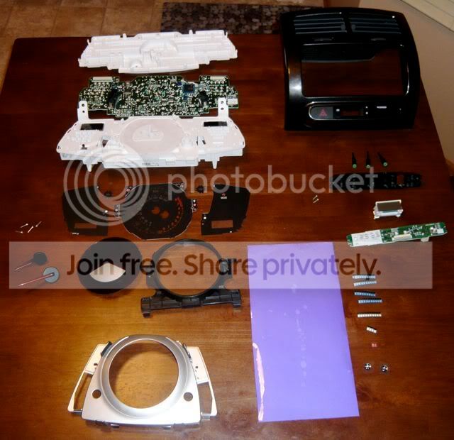
Here are all the parts once the gauge and clock are broken down!
Here is the Left side of the gauge cluster for anyone wondering what warning lights are located there for future swaps!
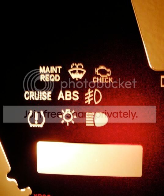
Here's the right side for the same purpose!

Here are all the tools to do the job as laid out so nicely in DIYs by Garage1217 and others with a couple minor changes. Old man glasses so I can see the tiny lil parts, and Eagle Rare Single Barrel Whiskey as I'm not a Jack Daniels fan and this could possibly be for during the mod, not after as recommended, depending on how things go!
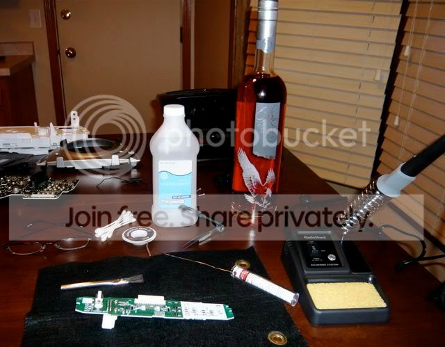
As you can see, I am going to use the clock as the learning piece, then reinstall it to ensure it works before doing the main gauge cluster. Figure messing that up would be cheaper than the main cluster! Wish Me luck!
Here are all the parts once the gauge and clock are broken down!
Here is the Left side of the gauge cluster for anyone wondering what warning lights are located there for future swaps!
Here's the right side for the same purpose!
Here are all the tools to do the job as laid out so nicely in DIYs by Garage1217 and others with a couple minor changes. Old man glasses so I can see the tiny lil parts, and Eagle Rare Single Barrel Whiskey as I'm not a Jack Daniels fan and this could possibly be for during the mod, not after as recommended, depending on how things go!
As you can see, I am going to use the clock as the learning piece, then reinstall it to ensure it works before doing the main gauge cluster. Figure messing that up would be cheaper than the main cluster! Wish Me luck!
Thread Starter
Senior Member
SL Member
Joined: Jan 2009
Posts: 203
OK... I did 4 LED's, 2 for the clock, 1 ea for air bag on and air bag off. I then plugged the board into the car. The red LED for the Emergency Flashers is on, none of mine are... Not sure what I am doing wrong if anything. I made sure the notch on the new LEDs went in the exact same as the old LEDs. Help Please if anyone has any valuable ideas! Gonna stop for tonight and contemplate life!

Thread Starter
Senior Member
SL Member
Joined: Jan 2009
Posts: 203
Originally Posted by DeathMachine
Make sure you dont have too much solder! I did my clock lights to blue and they work just fine... Make sure you didn't melt the LEDs by accident either...

Senior Member
SL Member
Joined: Nov 2007
Posts: 1,273
From: California
if you melt the LED, the two leads that are coming out of it will be discolored and also distorted in shape. VERY smart idea to practice on a clock first. knowing me i would have have dived right into it hahahah. but it looks like you got everything seperated and taken apart fine. the most important thing is to keep a steady hand, use small amounts of solder (very small....you dont want a blob, you just want a nice coat of melted solder on the leads/wires/whatever else you may be soldering) so keep that hand steady, stay focused, and make sure you get everything back together the way it was. looks like youre doing good. let us know how it turns out!!
Senior Member
SL Member
Joined: Nov 2007
Posts: 1,273
From: California
oh and one question. you said your first lights installed didn't work. how did you remove the previous lights? theres a method to unsoldering things, and (I'm only making assumptions now) maybe you uninstalled the standard lights improperly? if you left any of the original solder on the board, then theres a chance that that's dispersing the electrical output completely...again, I'm just making a guess. let me know how you unistalled the original lights and maybe we can work it out (hopefully along with the help of others who are more knowledgeable in the area!)
Thread Starter
Senior Member
SL Member
Joined: Jan 2009
Posts: 203
Ahhh... I used the method described by Garage1217 on his web site. I used the soldering iron to heat one edge of the solder and pull up the LED on that side, then using tweezers I heated the solder on the other side up and removed the LED. His instructions then say to drop a small amount of new solder on the connector on the board. I probably have too much solder, contaminated solder, too much heat, too shaky hands... I'll give those ones another shot this am. The only other thing I noted was that the LEDs on the main gauge have a band of solder along each edge. The ones in the clock assembly only have a dab in each corner, is it possible the LED's in the clock are different? The don't look different, and by the way, I tried swapping one of the stock ones back in, and that didn't work either!
Senior Member


SL Member
Team ScioNRG
Joined: Mar 2005
Posts: 5,920
From: Staten Island, NY
All done!
All 4 amber LEDs were swapped out for white LEDs
I did notice that the solder connections on the board were a little different than the tC's, BUT the same principles apply. Also, there is no direction of current flow on the board itself, so make sure you are putting the LEDs on the correct way.
I will take pictures tonight... its way too bright out now.
Coming next.... GAUGE CLUSTER!!!!!
Thread Starter
Senior Member
SL Member
Joined: Jan 2009
Posts: 203
Originally Posted by TheQuietThings
All done!
All 4 amber LEDs were swapped out for white LEDs
I did notice that the solder connections on the board were a little different than the tC's, BUT the same principles apply. Also, there is no direction of current flow on the board itself, so make sure you are putting the LEDs on the correct way.
I will take pictures tonight... its way too bright out now.
Coming next.... GAUGE CLUSTER!!!!!
All 4 amber LEDs were swapped out for white LEDs
I did notice that the solder connections on the board were a little different than the tC's, BUT the same principles apply. Also, there is no direction of current flow on the board itself, so make sure you are putting the LEDs on the correct way.
I will take pictures tonight... its way too bright out now.
Coming next.... GAUGE CLUSTER!!!!!
Thread Starter
Senior Member
SL Member
Joined: Jan 2009
Posts: 203
UPDATE! I feel better about my soldering skills now, the issue wasn't my soldering, at least not all of it. The LED in the clock on the xD al Plcc4 not plcc2 so they were automarically shorting by having a plcc2 placed in them. Gonna try a trick provided by Senor Garage1217... I have the wonderful assistance of another MN Scion owner that has actually done several LED swaps and things are starting to come together.
Thread Starter
Senior Member
SL Member
Joined: Jan 2009
Posts: 203
Do I hear a whoop? Yep, it's done, finito, complete, over, thats a wrap baby!
Perhaps I should have started with the cluster, as noted above, the clock is plcc4 LEDs and there is a trick to getting plcc2 LEDs to work in that location. You have to look to see which 2 of the 4 connectors are jumped, and then offset the LED a little and only solder the plcc2 LED to the other two connectors... It worked after some trial and error. I had the most excellent help of a Minneapolis Scikotics member that goes by the name of iaminsider in the Scikotics forum.
Here is the end result! Oh and if you are going to do the clock or passenger seat airbag lights in the center above the HVAC unit on the xD, make sure to order plcc4 LEDs. Garage1217 was also a great help as he IM'd for a bit on the technical issue of putting plcc2's in place of plcc4's, Thanks Garage!!!
 !
!
Perhaps I should have started with the cluster, as noted above, the clock is plcc4 LEDs and there is a trick to getting plcc2 LEDs to work in that location. You have to look to see which 2 of the 4 connectors are jumped, and then offset the LED a little and only solder the plcc2 LED to the other two connectors... It worked after some trial and error. I had the most excellent help of a Minneapolis Scikotics member that goes by the name of iaminsider in the Scikotics forum.
Here is the end result! Oh and if you are going to do the clock or passenger seat airbag lights in the center above the HVAC unit on the xD, make sure to order plcc4 LEDs. Garage1217 was also a great help as he IM'd for a bit on the technical issue of putting plcc2's in place of plcc4's, Thanks Garage!!!
!

Thread Starter
Senior Member
SL Member
Joined: Jan 2009
Posts: 203
Originally Posted by TRDxD
only for the guage's though....I think the clock / head unit interface and control dials would look much better with a blue or white. thats just me though 
Thread Starter
Senior Member
SL Member
Joined: Jan 2009
Posts: 203
Originally Posted by TRDxD
definitely!! did you do a swap for the head unit LEDs?