
Clock LED Modification


Thread Starter
Senior Member
SL Member
Joined: Jul 2004
Posts: 251
From: Mountain House, CA
Thanks hotbox, I'm guessing that they are 0805 SMD LED's. I'll eventually look into it. Good luck on the soldering, it's not hard actually, but you will need the proper equipment and lots of practice.
Thread Starter
Senior Member
SL Member
Joined: Jul 2004
Posts: 251
From: Mountain House, CA
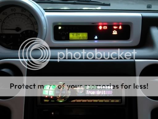
2 Max2k (aka the LED master)...That looks great. And yeah, the camera has the same effect on my white ones. The picture shows the individual led's brighter than if you were to see them in person. At night the light is diffused and looks great. I still recommend this method to anyone who wants to permanently change their clock color, rather than using markers.
I was planning on another project involoving replacing the LED's with RGB ones. I wanted to mimic the JDM 9 color change speedo by using either a PIC controller or pots to tune the backlight to different colors. But for now and the near future, this project will probably be put on hold because of priorities.
I was planning on another project involoving replacing the LED's with RGB ones. I wanted to mimic the JDM 9 color change speedo by using either a PIC controller or pots to tune the backlight to different colors. But for now and the near future, this project will probably be put on hold because of priorities.


Senior Member

SL Member
Team ScioNRG
Joined: Feb 2004
Posts: 5,274
From: Fortress of ScioNRG
Originally Posted by Max2k
It seems my edit button has disappeared.
thats why there is no edit button....

Senior Member
SL Member
Joined: Feb 2004
Posts: 2,650
From: Sipping haterade.
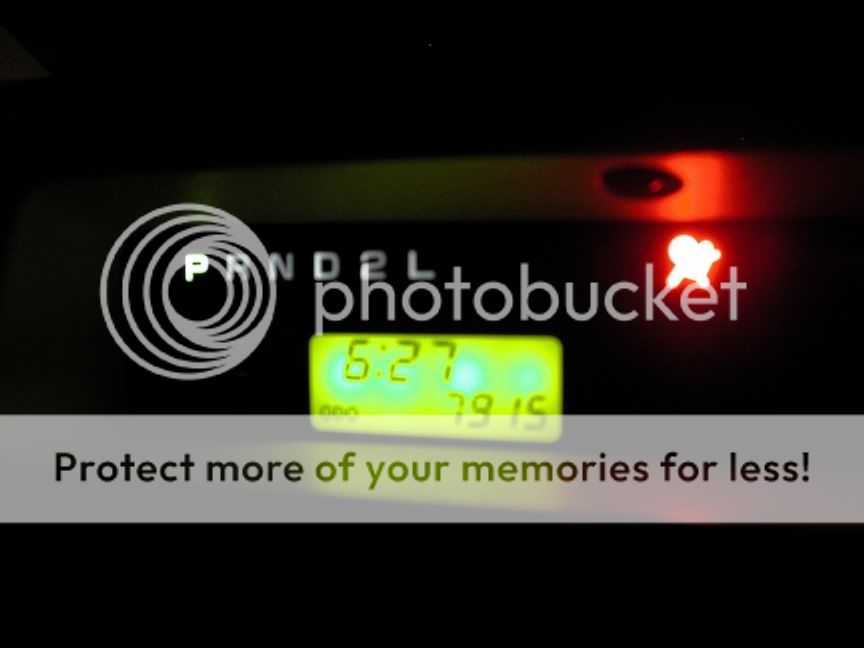
That's understandable, here's a more accurate picture:
This is pretty much what it actually looks like. You can see the 4 individual LEDs because they're brighter and bigger than the stock ones were.
Doing the 7 color gauges would be seriously sweet. I was just going to print out a new backing for them with light green substituted for the current orange in the fuel and tach hatch marks.


Member
SL Member
Joined: Dec 2004
Posts: 73
I just finished converting my clock to blue. I used these LEDs:
http://www.eled.com/product.asp?cata..._ID=EPL3015PBC
They were a tad too bright for me so I folded up a piece of wax paper and put it inside the hole behind the clock to help difuse the light. It looks really nice now. I will try to get pics up soon
Thanks for the excellent writeup!
http://www.eled.com/product.asp?cata..._ID=EPL3015PBC
They were a tad too bright for me so I folded up a piece of wax paper and put it inside the hole behind the clock to help difuse the light. It looks really nice now. I will try to get pics up soon
Thanks for the excellent writeup!


Junior Member
Joined: Jan 2005
Posts: 4
From: San Fernando Valley
Is there a specific polarity assignment on the board? top or bottom.

Senior Member
SL Member
Joined: Feb 2004
Posts: 635
From: Los Angeles
Getting a LED witha wide viewing angle will also help with more even light distribution. I saw some 1106 SMD online with 120 deg. of view. Also the luminescence is important. I would think in this type of application that its better to have a wide viewing angle then very strong luminescence. wgeee7478, what wavelength , Iv(mcd) type and Iv(mcd) min were you using?
Thread Starter
Senior Member
SL Member
Joined: Jul 2004
Posts: 251
From: Mountain House, CA
Most standard surface mount LED's have approx. 120 degrees of view. I purchased my LED's from a local electronic store and unfortunately they didn't have a data sheet to give me so I don't know the mcd values. However if what you are looking for is a more subtle diffused look you can get surface mount leds with a "diffused" lens rather than a "clear water" lens. Another method would be what was mentioned earlier and that is to use some semi-transparent paper (cookie baking sheet or tracing paper) directly behind the LCD screen to provide more of a light filter.

Senior Member
SL Member
Joined: Nov 2004
Posts: 161
From: Somwhere btwn Burbank and
Hey wgeee7478,
Well, I finally took a look at the speedo leds, and I have decided that I will not remove them. I am not good enough at soldering to remove those bad boys. As for the radio lights, there are just too damn many of them. Oh, well, maybe I will practice on something for a while first.
Well, I finally took a look at the speedo leds, and I have decided that I will not remove them. I am not good enough at soldering to remove those bad boys. As for the radio lights, there are just too damn many of them. Oh, well, maybe I will practice on something for a while first.
Thread Starter
Senior Member
SL Member
Joined: Jul 2004
Posts: 251
From: Mountain House, CA
Alright no problem, thanks for the effort. I would suggest old computer motherboards, video cards, network cards, memory module, etc... to get plenty of soldering practice. You won't be able to test it but at least you'll get to the point where at least the solder job looks professional. Just make sure you have the proper basic tools and then you can expand as you see fit.

