As everyone is aware, installing Blue LED's in the console of the TC (not sure about xa or xb) does not work well as far as brightness. The issue is forward voltage to drive these things. Most Blue (and white) require 3.3 or higher volts to obtain full lumins. Well, center console obviously does not offer this voltage. Amber, green, red, yellow LED's require 2.2v.... So, no problem getting really bright. :tap:
After spending hours of surfing my rear off...here is the deal regarding Blue LED's and White for that matter (since white is a blue led in theory). The lowerst voltage for a blue SMD led is currently made by Fairchild and was done for the mobil device market.
(snip)
September 12th, 2002––San Jose, CA––Fairchild Semiconductor (NYSE: FCS) today announces the introduction of three new, blue, compact, surface-mount LEDs. The three LEDs feature low voltage operation for low power consumption (Vf ≤ 3.15V @ 5mA) and a narrow forward voltage range (2.75 to 3.15V) for better color and brightness consistency. The small size and low power consumption make the LEDs ideal for lighting and illumination applications in compact, portable products.
(end snip)
So, 2.75 volts is the lowest available. Thats great as it would help the dim console issue. Problem is, in a PLCC design, the only thing Fairchild makes is a right angle LED. It should work if you look at the link:
Now, trying to find a distributer for them has been a problem. Any ideas
As for the console voltage, is there anyway we can get a schematic of the circuit board? The center console brightness is pot controlled from the gauge panel. I have a thought of taking the feed (should be one wire in the harness to console from gauge) and running this low voltage into a TTL circuit, then increasing this voltage by 1 volt and applying it back into the concole harness (which should still allow for pot control from gauge).
Any thoughts or help from experienced people out here?
HyperZ
07-01-2005, 03:08 PM
Not too much to add here, but I was wondering if it would be possible to use the same LED type that Toyota used for the temp knob. The blue LED they used is a different kind than what was used throughout the rest of the center console. Slightly larger, perhaps, but definitely brighter, which I'm sure was the point of putting it there. Would it be possible to find and use that same type of LED rather than the one we have all been using, or do you think it would cause problems with the circuitry?
jmiller20874
07-01-2005, 03:38 PM
^^^ I've thought about that myself but I don't think it would matter, here's why: The blue LED's I used are all dim except for the ones that light up when you press a toggle button (i.e. A/C, Recirc, both defrosts) are bright as they should be. It seems the LED's are bright until you have more than one or two in series.
ScionDad
07-01-2005, 03:54 PM
^^^ I've thought about that myself but I don't think it would matter, here's why: The blue LED's I used are all dim except for the ones that light up when you press a toggle button (i.e. A/C, Recirc, both defrosts) are bright as they should be. It seems the LED's are bright until you have more than one or two in series.
You're dead on jmiller. The voltage drops to about 2.6 volts...not enought for these blue LED's, but just fine for amber, green, etc. The A/C LED, etc are actually on a different voltage source.
Fsu1dolfan
07-01-2005, 04:07 PM
You guys have some good info here....i have done my gauges but still waiting to see what can be done for the center console??? If someone tries those new LEDs please post and give any info you can price, dealer, pics, pros cons.. I love reading this high tech stuff lol......props to you guys for trying to figure it out for us!!!
engifineer
07-01-2005, 04:22 PM
I was thinking along your lines with modifying the circuit, only using the variable voltage version of a 7405 regulator (cant remember the part number off hand). It would be a small (the smallest board available from Radio Crack) pcb with the regulator and a circuit to tie the POT in the dash to the control of the regulator.
Another idea is a simple base-biased transistor circuit to up the voltage a tad. These two ideas would offer fairly linear dimmer control like the stock system.
And of course there is our idea of finding the limiting resistors and resizing them.. but without a schematic it will take a while to trace the entire circuit.
I will also keep an eye out for a distributor of the LEDs you found. Thanks for sharing the info!
yellot00tr
07-01-2005, 04:39 PM
damnit-speak english. seriously, where the hell did u guys learn about this kinda stuff. :bow: :bow: if one of u guys figures this out, i'll buy ur blue leds for the center console when i buy mine.
Blue_Estel
07-01-2005, 09:12 PM
The last time I looked at the tC AC module I ohm'ed out the circuit for the 9 LED's and found the resistor for each circuit and the LED's they go to:
Hope that helps... I have limited access to the tC... I won't be able to look at this again until next week but hopefully you guys will get a little further with that info... I had all of the voltages written down but I can't find my notebook with all of that info :(
~chris
jmiller20874
07-01-2005, 09:40 PM
:ponder: Hmmm...so the resistor before each group of button LED's is 430ohm and the resistor before the LCD LED's is 330ohm (makes sense since the LCD is brighter than the buttons).
Then what if I replaced them with 100ohm or even just bridged them to remove them altogether, then would that work? Engifineer?
engifineer
07-01-2005, 10:45 PM
Hmmm.. are the LEDs in parallel? If so (meaning that D306 - 308 are tied together on both ends with the common point leading to the resistor) then we can simply drop the value of the resistor. So if the circuit looks like this:
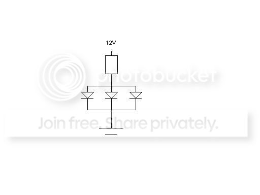
I would reccomend dropping the value of the resistor to 150 Ohms. I believe 100 may be pushing the max I limit of the LEDs.
However, I have not taken any measurements and am assuming that 12V is applied to the circuit when the dash lighting is at its brightest and that the LEDs are in parallel with each other sharing common load resistors. I picked 12V because that would yeild about 7 - 10mA through each LED in this configuration.
I will try to take mine apart this weekend. However, I moved into a new apartment and will be in the middle of unpacking, so not sure if I will get a chance. If anyone does, try to figure out if they are indeed configured as above and measure the voltage across the resistors (from one end of the resistor to the other, not to ground) and across the LEDs. Then, if the circuit is built as above, measure from the top of the resistor to the cathode (ground side) of the LEDs. These numbers will make it easy to re-design. If they are configured a different way let me know. I doubt they are in series, since a failure of one will cause the others to go out.
If each set of three LEDs are in series, then the 150 Ohm should work as well, but you could get away with 100 ohms in that case.
ScionDad
07-02-2005, 02:19 AM
Heh, heh, heh. It sure does help. I think you guys have a winner here. :clap: I am going with a 330 ohm and 2 each 430 ohm in parallel and work from there. I think that would be safe on the circuit and take no time to do. I'm thinking parallel
engifineer
07-02-2005, 02:28 AM
Heh, heh, heh. It sure does help. I think you guys have a winner here. :clap: I am going with a 330 ohm and 2 each 430 ohm in parallel and work from there. I think that would be safe on the circuit and take no time to do. I'm thinking parallel
Good thinking there. Adding them in parallel will be much easier than removing one and replacing with another. :bow:
kenwoodx2
07-02-2005, 02:54 AM
So for those of us less willing to monkey around with our gauges. Any clue to an aftermarket gauge coming out for the tC with blue illumination?
mushrew
07-02-2005, 03:00 AM
check out the thread about the same thing on clubsciontc's forums, some guy got around this buy physically raising the LEDs off the PCB using thick copper wire salvaged from a pair of jumper cables. they look just as bright as the dash when raised.
TurboMe
07-03-2005, 04:34 AM
u got a link to that?
I too appreciate u guys trying to figure this out.
engifineer
07-03-2005, 05:52 AM
So for those of us less willing to monkey around with our gauges. Any clue to an aftermarket gauge coming out for the tC with blue illumination?
Haven't heard of an aftermarket, but I would be happy to help out anyone who is thinking of modding theirs in my area (twin cities).
Good idea on raising the LEDs up off the board. Do they have pics of the results on that site?
engifineer
07-03-2005, 05:59 AM
Anyone have an idea of how much the gauge cluster board sells for? I have a couple of ideas for some lighting changes that will require me to construct a control circuit for them. I would need one I could play with for a while to determine sources for my inputs and outputs. Maybe something that could be available for others if I can get it all together. Just an idea (there is no nerdy emoticon on here or I would use it now :P )
i remember there being more pics on the guys website i guess click on his profile or something to find the link, i don'jt have it handy
Wow, those actually came out nice! I think you could even make them further away and still look ok. Looking at it from the part of me that believes to do it the most efficient and simple way, that is the way to go... Of course, there is that geeky, tech guy part of me that still wants to redisign it to make it work that way as well... but then again, I guess I am a tech geek :P
Thanks for posting !
mushrew
07-03-2005, 07:52 AM
it'd be nice if there was just one huge forum for tC stuff...kinda annoying having to surf scionlife, yoursciontc and clubsctiontc to figure everything out =P
TurboMe
07-03-2005, 11:27 AM
so it looks like a lot of them are just somehow extended the LED to bring them closer to the button. One guy used a copper wire extention and another guys used tubes. I will would feel a lot better if someone could find out a way to fix the power source. :pray:
Greenbeanboy12
07-05-2005, 06:31 PM
:clap: :bow:
dirty_disco
07-09-2005, 03:34 AM
Looks like mouser.com has these new low voltage LED's in stock. Here's the link - http://www.mouser.com/index.cfm?&handler=data.listcategory&Ne=3&terms=QTLP610C-EB&Ntt=*QTLP610CEB*&Ns=SField&N=51210000&crc=true
The only thing I'm not sure about with these LED's is that they are rated from 8-16 mcd at 2.75 - 2.95 v. The LED's from (http://www.lc-led.com/View/itemNumber/98) are rated from 350 mcd at 3.0 v. That's a pretty big difference in the luminous intensity. These new LED's still might not be as bright as we want. I'm no expert though and I guess the only way to know for sure is to see for ourselves.
engifineer
07-09-2005, 06:51 AM
They would not be too bright, not even enough to be useable most likely. Ours are rated for 350 mcd (the blues in my case) but with the voltages and currents supplied are probably operating aroud 250 mcd I would guess. So those would be way too dim I am afraid.
The other issue is that they are right angle type LEDs, so you would have to be able to solder them upright, which is very possible, but more of a hassle.
They do have a 120 degree view angle, which should work just fine, but the intensity is the real killer here.
Thanks though for sharing the info! It is good to know there are more people looking into this!
What we need is the following:
View angle of at least 120 degrees (maybe less, but I think less would start to show dim areas between LEDs)
Intensity of approximately 250 - 350 mcd
Vf around 2.6 - 2.8 volts
dirty_disco
07-09-2005, 03:24 PM
Yeah, after doing some more resaerch and spending some more time scouring the net I've just decided to make some wire stilts for the console led's. The other thing I noticed about these low voltage is that they are sapphire blue and not pure blue. Looking at the pics of the devices in the article on them I don't think the color would match up with the blue in the gauges. Unfortunatley I have no real training in electronics. I'm just a computer geek with a enough knowledge to be dangerous in this area. I think the only way we're going to get around this problem is to figure out a way to increase the voltage to these led's. I had to pick up a new console since I ended up cracking my lcd screen the first time around. If anyone would like this spare console board to experiment with let me know. I got it from ebay which saved me some cash from the dealer price for a replacement. I'd be willing to give up the board for small donation fee. :wink:
ScionDad
07-11-2005, 05:16 PM
Yeah, after doing some more resaerch and spending some more time scouring the net I've just decided to make some wire stilts for the console led's. The other thing I noticed about these low voltage is that they are sapphire blue and not pure blue. Looking at the pics of the devices in the article on them I don't think the color would match up with the blue in the gauges. Unfortunatley I have no real training in electronics. I'm just a computer geek with a enough knowledge to be dangerous in this area. I think the only way we're going to get around this problem is to figure out a way to increase the voltage to these led's. I had to pick up a new console since I ended up cracking my lcd screen the first time around. If anyone would like this spare console board to experiment with let me know. I got it from ebay which saved me some cash from the dealer price for a replacement. I'd be willing to give up the board for small donation fee. :wink:
PMed you :bow:
O5_TRD_tC
08-01-2005, 06:16 PM
any updates?
engifineer
08-10-2005, 10:08 PM
I believe I should be recieving a loaner center console to test with today (Fedex delivered a package to my place today, I just havent been home yet). Thanks, by the way to ScionDad for sending it so I could play around with it :bow: He has been pretty busy and has not had time for it lately, so I thought I would take a shot at it.
I plan on determining which size resistors I need and obtaining them this week (I will probably have to order them since they are smt) and testing out the final design. Hopefully, by next week I will have a solution for our notorius dim-button problem. I will update everyone when I have it complete!
engifineer
08-11-2005, 02:51 AM
Just a quick update...
I recieved the console (thanks for the extras ScionDad! I owe you for that one!), tested and drew out the entire lighting schematic and got about half the LEDs switched out. I traced out every LED except the Security and Passenger Belt lights. I will post the diagram and values once I put them into MicroSim, as I am sure some would find them useful. Before I soldered anything I swapped it for mine and took some measurements to calculate from.
They are powering those LEDs off MUCH less than I expected. It appears the minimum forward voltage drop is very low. Right now each LED is recieving just over .5 V. So the fact that the blues light even as much as they do tells me that running them wide open (which we couldnt off of 7.5V, the entire branch voltage for each group) would be much brighter than we realize. So I am going to try a couple of things to find the brightness that matches the gauges and interior the best. I dont want them glaring over the gauge cluster, as that would be tacky looking really. I want to make them all look even.
I will solder in a couple of potentiometers or just try a couple of sized resistors tomorrow after work to find the correct brightness. I plan to have it by the weekend at the latest.
Just thought I would give a quick update!
mushrew
08-11-2005, 02:55 AM
thanks for the update!
dirty_disco
08-11-2005, 03:24 AM
That's great news...Glad to hear it...
mandos
08-11-2005, 04:03 PM
Coming closer and closer to making me drive to Minneapolis I see ;)
engifineer
08-11-2005, 07:23 PM
Coming closer and closer to making me drive to Minneapolis I see ;)
:D I hope to have it ready soon... so we could do the gauges AND dash then!
Its raining here today.. so even more reason to stay inside and finish it. I will at least get all the LEDs installed and the schematic finished tonight... but I also plan on hooking it up again with some test resistors to determine the proper size. I'll post an update then.
mandos
08-11-2005, 08:18 PM
Coming closer and closer to making me drive to Minneapolis I see ;)
:D I hope to have it ready soon... so we could do the gauges AND dash then!
Its raining here today.. so even more reason to stay inside and finish it. I will at least get all the LEDs installed and the schematic finished tonight... but I also plan on hooking it up again with some test resistors to determine the proper size. I'll post an update then.
Was raining something vicious last night/this morning...now hot and humid as usual.
Glad to see progress coming good on this...I'm tired of amber and don't trust myself w/ solder, I'll cut holes in my car...but no solder ;)
engifineer
08-12-2005, 02:36 AM
Ok, I did some testing.. then some more.. then some documenting...
The LEDs for the buttons (other than the ones that come on when you push a button) have a total supply of 7.95V for each group of three. This poses an issue. The ambers that were in there dropped just over .5v (very different from the ambers at LC-LED). Our blues drop 2.6 minimum. Three of these in series make 7.8V, so even shorting the resistor does not make any noticeable difference, as the current is minimally effected. So, here is my idea:
I am going to isolate one LED from each branch of three, and tap its supply from the top of the branch, effectively placing that one in parallel with the other two. That means I will have to add a resistor to the board for the third LED. This will provide enough over voltage for each to allow the amount of current needed for them. I hope this makes some sense.. I had a LOOOONG day at work and have been working on this sense... until I stopped for a couple of rums just now (meaning I am through working for the night :P )
I will calculate to have equal currents through them all so they are the same brightness. The ones for the buttons I think are bright enough.. hopefully they are. They have their cathodes connected to the collector of what I think is a base-emitter biased transistor. Put simply, that will regulate the current through the LED preventing it from being any brighter regardless of resistor changes (at least that is how it looks so far). But as I said, these are brighter anyway so I will see if they word as is.
The three for the clock are also transitor controlled, so I will have to see how they come out. The test console does not have a clock on it.. so someone tell me how bright it turns out that has tried it?
I will look into it again tomorrow or sat morning and see if my ideas pan out. I lose the power for the buttons in concern when tracing the circuit (I think it is a 3 layer board, this is very common.) . As long as they are not controlled by a constant current source too, which I do not think they are, we should be in luck. If I am right it will be a matter of cutting a couple of traces and running new ones via added resistors to the sources. A 1/16 watt radial axial lead resistor should work perfectly.
Anyway, hope I didnt ramble off into geek land too far there :P I will post another update soon.
engifineer
08-12-2005, 02:38 AM
Thought I would post the schematic for the LEDs in case anyone is interested in having them. I stopped at the transistors and did not include other systems on the board or the security and pass. belt lights. I also just used BLUE leds in the schematics..
Just found out more. The main power for the buttons is drawn from a voltage (not current) regulator. A TA7808F to be specific. I believe this will still provide the current needed when I rewire as I mentioned above. So unless I run into something else I should have a solution...
fishingexpert87
08-12-2005, 03:48 AM
my friend viro has an idea that hes gonna try out, he said he is going to run a wire from where the brightest led starts to the last led (3rd led up) which might help with the voltage, i will see whats up with him if he did it or not!
engifineer
08-12-2005, 04:01 AM
That is similar to what I am doing, but resistance will need to be added to balance them out and prevent burning out the LED. So for the top left branch of three above for example, I will tied the cathode of D307 to the cathode of D308, bypassing D309 and leaving an extra 2.6V for D307 and D308 to play with. I can then also drop the value of R304 to make those two even brighter if needed. Then, I will cut the connection from the cathode of D308 and tie it on the supply side (right side in the schematic) of R304 via the proper size resistor. Its resistor should be roughly twice the resistance of R304's value to balance them all out.
ScionDad
08-12-2005, 04:08 AM
Great Job :bow: It should be a pretty easy fix in the future to do all at once with the LED's. I nominate this one for the August SL mod contest. Knocking out a problem mod that has lasted a year. :clap: Alot of peeps will be pleased with your results.
engifineer
08-12-2005, 04:27 AM
Thanks for the good words! Here is the modified schematic for those interested. Keep in mind I need to test this, but I think this will get us there as long as the regulator can handle it (which I am sure it can). It shows the modifed circuit, added R1 - R4 and swapped out R304, R306 and R310. We can keep our fingers crossed anyway...
I just finished modifying the circuit for the upper left three buttons and testing them. Here are a couple of pictures. I blocked out the dial and spot for the clock because neiter are in, so those LEDs drown the camera shot unless I cover them. Once gives a comparison with the gauge lights. I think they will match perfectly! When I complete the rest I will post a full write up and pictures.
Will this be the same if someone were to go with white?
engifineer
08-13-2005, 01:14 AM
That looks great!
Will this be the same if someone were to go with white?
It should be the same setup with the white.. but I have not seen white in the center console so I am not sure how dim they are to begin with. Some colors may work better than others.
I'll post pics of the whole thing later when it is complete!
I did end up using different sized resistors than I originally figured for, so I will post the new values as well once I know it all looks right.
ScionDad
08-13-2005, 05:28 AM
Bam,,,,,You're the MAN. :clap: That looks SWEET :shock: I guess after seeing it Blue and dim for 7 months...WOW. :bow:
ScionDad
08-13-2005, 05:30 AM
Bam,,,,,You're the MAN. :clap: That looks SWEET :shock: I guess after seeing it Blue and dim for 7 months...WOW. :bow:
ScionDad
08-13-2005, 05:30 AM
Bam,,,,,You're the MAN. :clap: That looks SWEET :shock: I guess after seeing it Blue and dim for 7 months...WOW. :bow:
ScionDad
08-13-2005, 05:30 AM
Bam,,,,,You're the MAN. :clap: That looks SWEET :shock: I guess after seeing it Blue and dim for 7 months...WOW. :bow:
ScionDad
08-13-2005, 05:30 AM
Bam,,,,,You're the MAN. :clap: That looks SWEET :shock: I guess after seeing it Blue and dim for 7 months...WOW. :bow:
engifineer
08-13-2005, 07:36 AM
Here it is.. complete! I soldered my LCD on it to see how it looks. I would have liked to have had smaller resistors on hand.. but the 1/8 W is the smallest I had and worked great. I am in the process of getting some smaller ones and more LEDs and I will ship the other one complete back to you ScionDad, you should just have to solder on your LCD and pop it in! . Thanks for letting me borrow it! I want to drive with them for a couple of days anyway to make sure all connections are good, power supplies are OK, etc. But Everything measured out good when I was finshed. I will post the pics of the board and a full write-up of how it is done this weekend, probably tomorrow.. but here are some pics...
wow... nice... i have ordered my leds and will do it soon... waiting for a nice write-up about making them not dim anymore! thanks! props to engifineer!! you should do blue for the head unit also...
tChillin
08-13-2005, 07:15 PM
Nice Job man! Thanks for looking into this, I just never had the time to. Hope to get a "How to" soon. :clap:
mandos
08-13-2005, 07:35 PM
Well, now to scrounge up the cash ;)
Also...FRIGGIN SWEET.
viro
08-13-2005, 08:28 PM
Hey engifineer.. seems like you and i where working on the same thing at the same time... i have them done already (pics below) but i didn't used any resistance... i just changed the circuit to series-parallel instead of a whole series and it works just fine....
By the way... engifineer i screwed up my lcd by hitting it accidentaly with the plier... if you know where can i get a replacement please let me know...
engifineer i will do a diagram of how i got it done so you can check it and tell me if what i did is right or not.... based on some numbers that i threw in, 8 of my bulbs are supposed to be working with 5.6V and four of them working with 2.8V (5.6/2).
Check the pics below.
http://i12.photobucket.com/albums/a206/ViroScion/DSCN0910.jpg
http://i12.photobucket.com/albums/a206/ViroScion/DSCN0907.jpg
http://i12.photobucket.com/albums/a206/ViroScion/DSCN0915.jpg
[/img]
viro
08-13-2005, 09:09 PM
Here is the diagram of how i got it done... please check it engifineer.... any comments are welcome....
Please someone that knows about a LCD screen please let me know....
^^ Looks good! I added the resistance to keep from killing the 7808 regulator or burning the LEDs up sooner than later. I wanted to make them as bright as the gauges without drawing any more current than necessary. There should be some headroom at the regulator, but I did not want to push it too hard. It looks like you ran your bottom LED in parallel with the second one? I did that with the blue and there was a definite noticeable difference in brightness between them (which may not be so noticeable with the white), so I worked on it a little so they are all operating on the same forward current.
A little LED info for everyone interested: Do keep in mind on your voltages that the LEDs will always read approx 2.6 - 2.8 V across them (for the blues and whites we use). An LED has very high resistance untill its minimum forward voltage is reached. At that point, that voltage (2.6V here) is dropped accross the LED, and the rest is dropped across your wiring (which has very very low resistance) So to figure the current through the circuit you divide whats left of the circuit voltage after the LED is subtracted and divide that by the other resistances in the circuit. So if you apply 5V, lets say, to a 2.6V LED and use no resistance in series, your circuit current is 2.4V/(near zero resistance), which is very high. This is why we always want a resistance in series with the LEDs. For the clock I actually shorted across the resistor, but they are in series, so the voltage is almost exactly equal to the three forward voltages, so the measure current through those three are actuall approx 1mA believe it or not!
I am in the middle of some stuff today, but will work on a full write up as I can, hopefully today. Thanks for the good words!
engifineer
08-13-2005, 09:11 PM
Here is the diagram of how i got it done... please check it engifineer.... any comments are welcome....
Please someone that knows about a LCD screen please let me know....
I think I figured out how you did it. You ran the third LED in parallel with the second, right?
If so, you are ok current wise I think. I tried this with the blues, but I could notice a difference in brightness. However, white is composed of the whole spectrum, so the filter on the buttons will make that less noticeable than with a more pure color such as blue. As I mentioned, with the blue I could tell a difference due to there being twice as much current flowing through the top LED compared to the two in parallel. Good work though!
viro
08-14-2005, 09:05 AM
Hey guys... note that some of the factory printed connector are interrupted... i did this by leaving that same side of the LED unsoldered and putting some electrical tape under the LED to avoid contact with the board... here is a blurry picture of this... if u are smart you will figure it out....
IF YOU GUYS KNOW ABOUT SOMEBODY WITH A LCD SCREEN THAT I CAN BUY,LEASE, RENT OR WHATEVER FROM HIM... LET ME KNOW PLEASE....
iF ANYONE WANTS ME TO DO THIS MOD FOR THEM WE CAN WORK IT OUT... I NEED A NEW LCD SCREEN AND THERE IS ONE CENTER CONSOLE ON EBAY RUNNING ABOUT 130 DOLLARS... IF I HAVE SOMEONE THAT WANTS SPLIT COST WITH ME WE CAN DO SOMETHING AND I WILL SHIP TO THAT PERSON THE WHOLE CENTER CONSOLE ALREADY MODIFIED WITH THE COLOR OF YOUR CHOICE FOR A VERY REASONABLE PRICE... ALL THAT WILL NEED TO BE DONE IS TO SOLDER YOUR LCD SCREEN TO THE MODIFIED BOARD....
Will do that or something that can work... i not even know... i think that seeing my screen like that is driving me crazy... i'm desperate... some one with help or interested on some trade like the one above just let me know please.....