


BLUE Led conversion people - Problem/Solution!?


Senior Member


Team ScionEyed
SL Member
Joined: Feb 2005
Posts: 1,552

so it looks like a lot of them are just somehow extended the LED to bring them closer to the button. One guy used a copper wire extention and another guys used tubes. I will would feel a lot better if someone could find out a way to fix the power source. 


Junior Member
Joined: Feb 2005
Posts: 11
From: Jax, Fl
Looks like mouser.com has these new low voltage LED's in stock. Here's the link - http://www.mouser.com/index.cfm?&han...10000&crc=true
The only thing I'm not sure about with these LED's is that they are rated from 8-16 mcd at 2.75 - 2.95 v. The LED's from (http://www.lc-led.com/View/itemNumber/98) are rated from 350 mcd at 3.0 v. That's a pretty big difference in the luminous intensity. These new LED's still might not be as bright as we want. I'm no expert though and I guess the only way to know for sure is to see for ourselves.
The only thing I'm not sure about with these LED's is that they are rated from 8-16 mcd at 2.75 - 2.95 v. The LED's from (http://www.lc-led.com/View/itemNumber/98) are rated from 350 mcd at 3.0 v. That's a pretty big difference in the luminous intensity. These new LED's still might not be as bright as we want. I'm no expert though and I guess the only way to know for sure is to see for ourselves.

Senior Member
Scikotics
SL Member
Joined: Nov 2004
Posts: 9,731
From: Minneapolis, MN
They would not be too bright, not even enough to be useable most likely. Ours are rated for 350 mcd (the blues in my case) but with the voltages and currents supplied are probably operating aroud 250 mcd I would guess. So those would be way too dim I am afraid.
The other issue is that they are right angle type LEDs, so you would have to be able to solder them upright, which is very possible, but more of a hassle.
They do have a 120 degree view angle, which should work just fine, but the intensity is the real killer here.
Thanks though for sharing the info! It is good to know there are more people looking into this!
What we need is the following:
View angle of at least 120 degrees (maybe less, but I think less would start to show dim areas between LEDs)
Intensity of approximately 250 - 350 mcd
Vf around 2.6 - 2.8 volts
The other issue is that they are right angle type LEDs, so you would have to be able to solder them upright, which is very possible, but more of a hassle.
They do have a 120 degree view angle, which should work just fine, but the intensity is the real killer here.
Thanks though for sharing the info! It is good to know there are more people looking into this!
What we need is the following:
View angle of at least 120 degrees (maybe less, but I think less would start to show dim areas between LEDs)
Intensity of approximately 250 - 350 mcd
Vf around 2.6 - 2.8 volts
Junior Member
Joined: Feb 2005
Posts: 11
From: Jax, Fl
Yeah, after doing some more resaerch and spending some more time scouring the net I've just decided to make some wire stilts for the console led's. The other thing I noticed about these low voltage is that they are sapphire blue and not pure blue. Looking at the pics of the devices in the article on them I don't think the color would match up with the blue in the gauges. Unfortunatley I have no real training in electronics. I'm just a computer geek with a enough knowledge to be dangerous in this area. I think the only way we're going to get around this problem is to figure out a way to increase the voltage to these led's. I had to pick up a new console since I ended up cracking my lcd screen the first time around. If anyone would like this spare console board to experiment with let me know. I got it from ebay which saved me some cash from the dealer price for a replacement. I'd be willing to give up the board for small donation fee. 

Thread Starter
Senior Member
SL Member
Joined: Feb 2005
Posts: 2,087
From: St. Louis, MO
Originally Posted by dirty disco
Yeah, after doing some more resaerch and spending some more time scouring the net I've just decided to make some wire stilts for the console led's. The other thing I noticed about these low voltage is that they are sapphire blue and not pure blue. Looking at the pics of the devices in the article on them I don't think the color would match up with the blue in the gauges. Unfortunatley I have no real training in electronics. I'm just a computer geek with a enough knowledge to be dangerous in this area. I think the only way we're going to get around this problem is to figure out a way to increase the voltage to these led's. I had to pick up a new console since I ended up cracking my lcd screen the first time around. If anyone would like this spare console board to experiment with let me know. I got it from ebay which saved me some cash from the dealer price for a replacement. I'd be willing to give up the board for small donation fee.


Senior Member
Scikotics
SL Member
Joined: Nov 2004
Posts: 9,731
From: Minneapolis, MN
I believe I should be recieving a loaner center console to test with today (Fedex delivered a package to my place today, I just havent been home yet). Thanks, by the way to ScionDad for sending it so I could play around with it He has been pretty busy and has not had time for it lately, so I thought I would take a shot at it.
I plan on determining which size resistors I need and obtaining them this week (I will probably have to order them since they are smt) and testing out the final design. Hopefully, by next week I will have a solution for our notorius dim-button problem. I will update everyone when I have it complete!
He has been pretty busy and has not had time for it lately, so I thought I would take a shot at it. I plan on determining which size resistors I need and obtaining them this week (I will probably have to order them since they are smt) and testing out the final design. Hopefully, by next week I will have a solution for our notorius dim-button problem. I will update everyone when I have it complete!
Senior Member
Scikotics
SL Member
Joined: Nov 2004
Posts: 9,731
From: Minneapolis, MN
Just a quick update...
I recieved the console (thanks for the extras ScionDad! I owe you for that one!), tested and drew out the entire lighting schematic and got about half the LEDs switched out. I traced out every LED except the Security and Passenger Belt lights. I will post the diagram and values once I put them into MicroSim, as I am sure some would find them useful. Before I soldered anything I swapped it for mine and took some measurements to calculate from.
They are powering those LEDs off MUCH less than I expected. It appears the minimum forward voltage drop is very low. Right now each LED is recieving just over .5 V. So the fact that the blues light even as much as they do tells me that running them wide open (which we couldnt off of 7.5V, the entire branch voltage for each group) would be much brighter than we realize. So I am going to try a couple of things to find the brightness that matches the gauges and interior the best. I dont want them glaring over the gauge cluster, as that would be tacky looking really. I want to make them all look even.
I will solder in a couple of potentiometers or just try a couple of sized resistors tomorrow after work to find the correct brightness. I plan to have it by the weekend at the latest.
Just thought I would give a quick update!
I recieved the console (thanks for the extras ScionDad! I owe you for that one!), tested and drew out the entire lighting schematic and got about half the LEDs switched out. I traced out every LED except the Security and Passenger Belt lights. I will post the diagram and values once I put them into MicroSim, as I am sure some would find them useful. Before I soldered anything I swapped it for mine and took some measurements to calculate from.
They are powering those LEDs off MUCH less than I expected. It appears the minimum forward voltage drop is very low. Right now each LED is recieving just over .5 V. So the fact that the blues light even as much as they do tells me that running them wide open (which we couldnt off of 7.5V, the entire branch voltage for each group) would be much brighter than we realize. So I am going to try a couple of things to find the brightness that matches the gauges and interior the best. I dont want them glaring over the gauge cluster, as that would be tacky looking really. I want to make them all look even.
I will solder in a couple of potentiometers or just try a couple of sized resistors tomorrow after work to find the correct brightness. I plan to have it by the weekend at the latest.
Just thought I would give a quick update!

Senior Member
Scikotics
SL Member
Joined: Nov 2004
Posts: 9,731
From: Minneapolis, MN
Originally Posted by mandos
Coming closer and closer to making me drive to Minneapolis I see ;)
Its raining here today.. so even more reason to stay inside and finish it. I will at least get all the LEDs installed and the schematic finished tonight... but I also plan on hooking it up again with some test resistors to determine the proper size. I'll post an update then.

Former Sponsor

SL Member
Scinergy
Joined: Jan 2005
Posts: 2,205
From: Newton, IA
Originally Posted by engifineer
Originally Posted by mandos
Coming closer and closer to making me drive to Minneapolis I see ;)
Its raining here today.. so even more reason to stay inside and finish it. I will at least get all the LEDs installed and the schematic finished tonight... but I also plan on hooking it up again with some test resistors to determine the proper size. I'll post an update then.
Glad to see progress coming good on this...I'm tired of amber and don't trust myself w/ solder, I'll cut holes in my car...but no solder ;)
Senior Member
Scikotics
SL Member
Joined: Nov 2004
Posts: 9,731
From: Minneapolis, MN
Ok, I did some testing.. then some more.. then some documenting...
The LEDs for the buttons (other than the ones that come on when you push a button) have a total supply of 7.95V for each group of three. This poses an issue. The ambers that were in there dropped just over .5v (very different from the ambers at LC-LED). Our blues drop 2.6 minimum. Three of these in series make 7.8V, so even shorting the resistor does not make any noticeable difference, as the current is minimally effected. So, here is my idea:
I am going to isolate one LED from each branch of three, and tap its supply from the top of the branch, effectively placing that one in parallel with the other two. That means I will have to add a resistor to the board for the third LED. This will provide enough over voltage for each to allow the amount of current needed for them. I hope this makes some sense.. I had a LOOOONG day at work and have been working on this sense... until I stopped for a couple of rums just now (meaning I am through working for the night )
)
I will calculate to have equal currents through them all so they are the same brightness. The ones for the buttons I think are bright enough.. hopefully they are. They have their cathodes connected to the collector of what I think is a base-emitter biased transistor. Put simply, that will regulate the current through the LED preventing it from being any brighter regardless of resistor changes (at least that is how it looks so far). But as I said, these are brighter anyway so I will see if they word as is.
The three for the clock are also transitor controlled, so I will have to see how they come out. The test console does not have a clock on it.. so someone tell me how bright it turns out that has tried it?
I will look into it again tomorrow or sat morning and see if my ideas pan out. I lose the power for the buttons in concern when tracing the circuit (I think it is a 3 layer board, this is very common.) . As long as they are not controlled by a constant current source too, which I do not think they are, we should be in luck. If I am right it will be a matter of cutting a couple of traces and running new ones via added resistors to the sources. A 1/16 watt radial axial lead resistor should work perfectly.
Anyway, hope I didnt ramble off into geek land too far there I will post another update soon.
The LEDs for the buttons (other than the ones that come on when you push a button) have a total supply of 7.95V for each group of three. This poses an issue. The ambers that were in there dropped just over .5v (very different from the ambers at LC-LED). Our blues drop 2.6 minimum. Three of these in series make 7.8V, so even shorting the resistor does not make any noticeable difference, as the current is minimally effected. So, here is my idea:
I am going to isolate one LED from each branch of three, and tap its supply from the top of the branch, effectively placing that one in parallel with the other two. That means I will have to add a resistor to the board for the third LED. This will provide enough over voltage for each to allow the amount of current needed for them. I hope this makes some sense.. I had a LOOOONG day at work and have been working on this sense... until I stopped for a couple of rums just now (meaning I am through working for the night
) I will calculate to have equal currents through them all so they are the same brightness. The ones for the buttons I think are bright enough.. hopefully they are. They have their cathodes connected to the collector of what I think is a base-emitter biased transistor. Put simply, that will regulate the current through the LED preventing it from being any brighter regardless of resistor changes (at least that is how it looks so far). But as I said, these are brighter anyway so I will see if they word as is.
The three for the clock are also transitor controlled, so I will have to see how they come out. The test console does not have a clock on it.. so someone tell me how bright it turns out that has tried it?
I will look into it again tomorrow or sat morning and see if my ideas pan out. I lose the power for the buttons in concern when tracing the circuit (I think it is a 3 layer board, this is very common.) . As long as they are not controlled by a constant current source too, which I do not think they are, we should be in luck. If I am right it will be a matter of cutting a couple of traces and running new ones via added resistors to the sources. A 1/16 watt radial axial lead resistor should work perfectly.
Anyway, hope I didnt ramble off into geek land too far there
I will post another update soon.
Senior Member
Scikotics
SL Member
Joined: Nov 2004
Posts: 9,731
From: Minneapolis, MN
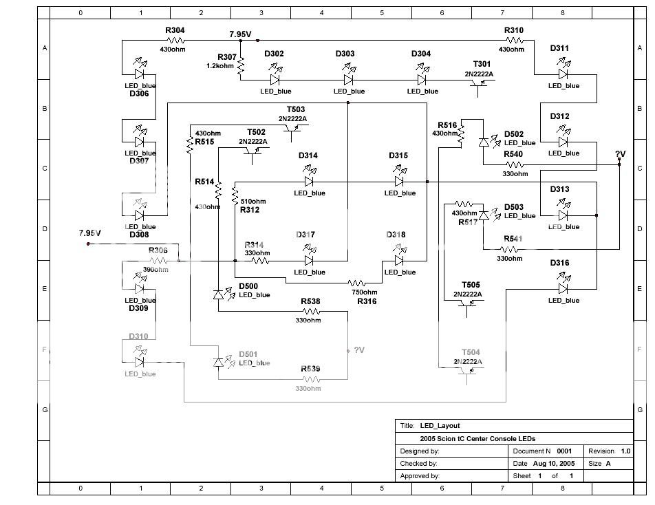
Thought I would post the schematic for the LEDs in case anyone is interested in having them. I stopped at the transistors and did not include other systems on the board or the security and pass. belt lights. I also just used BLUE leds in the schematics..
Senior Member
Scikotics
SL Member
Joined: Nov 2004
Posts: 9,731
From: Minneapolis, MN
Just found out more. The main power for the buttons is drawn from a voltage (not current) regulator. A TA7808F to be specific. I believe this will still provide the current needed when I rewire as I mentioned above. So unless I run into something else I should have a solution...

Senior Member
SL Member
Scion Evolution
Joined: Jun 2005
Posts: 1,654
From: Florida
my friend viro has an idea that hes gonna try out, he said he is going to run a wire from where the brightest led starts to the last led (3rd led up) which might help with the voltage, i will see whats up with him if he did it or not!
Senior Member
Scikotics
SL Member
Joined: Nov 2004
Posts: 9,731
From: Minneapolis, MN
That is similar to what I am doing, but resistance will need to be added to balance them out and prevent burning out the LED. So for the top left branch of three above for example, I will tied the cathode of D307 to the cathode of D308, bypassing D309 and leaving an extra 2.6V for D307 and D308 to play with. I can then also drop the value of R304 to make those two even brighter if needed. Then, I will cut the connection from the cathode of D308 and tie it on the supply side (right side in the schematic) of R304 via the proper size resistor. Its resistor should be roughly twice the resistance of R304's value to balance them all out.
Thread Starter
Senior Member
SL Member
Joined: Feb 2005
Posts: 2,087
From: St. Louis, MO
Great Job It should be a pretty easy fix in the future to do all at once with the LED's. I nominate this one for the August SL mod contest. Knocking out a problem mod that has lasted a year.  Alot of peeps will be pleased with your results.
It should be a pretty easy fix in the future to do all at once with the LED's. I nominate this one for the August SL mod contest. Knocking out a problem mod that has lasted a year. Alot of peeps will be pleased with your results.