


BLUE Led conversion people - Problem/Solution!?


Thread Starter
Senior Member


SL Member
Joined: Feb 2005
Posts: 2,087
From: St. Louis, MO
 BLUE Led conversion people - Problem/Solution!?
As everyone is aware, installing Blue LED's in the console of the TC (not sure about xa or xb) does not work well as far as brightness. The issue is forward voltage to drive these things. Most Blue (and white) require 3.3 or higher volts to obtain full lumins. Well, center console obviously does not offer this voltage. Amber, green, red, yellow LED's require 2.2v.... So, no problem getting really bright. 
After spending hours of surfing my rear off...here is the deal regarding Blue LED's and White for that matter (since white is a blue led in theory). The lowerst voltage for a blue SMD led is currently made by Fairchild and was done for the mobil device market.
(snip)
September 12th, 2002––San Jose, CA––Fairchild Semiconductor (NYSE: FCS) today announces the introduction of three new, blue, compact, surface-mount LEDs. The three LEDs feature low voltage operation for low power consumption (Vf ≤ 3.15V @ 5mA) and a narrow forward voltage range (2.75 to 3.15V) for better color and brightness consistency. The small size and low power consumption make the LEDs ideal for lighting and illumination applications in compact, portable products.
(end snip)
So, 2.75 volts is the lowest available. Thats great as it would help the dim console issue. Problem is, in a PLCC design, the only thing Fairchild makes is a right angle LED. It should work if you look at the link:
http://www.fairchildsemi.com/news/20...9/blueled.html
Now, trying to find a distributer for them has been a problem. Any ideas
As for the console voltage, is there anyway we can get a schematic of the circuit board? The center console brightness is pot controlled from the gauge panel. I have a thought of taking the feed (should be one wire in the harness to console from gauge) and running this low voltage into a TTL circuit, then increasing this voltage by 1 volt and applying it back into the concole harness (which should still allow for pot control from gauge).
Any thoughts or help from experienced people out here?
After spending hours of surfing my rear off...here is the deal regarding Blue LED's and White for that matter (since white is a blue led in theory). The lowerst voltage for a blue SMD led is currently made by Fairchild and was done for the mobil device market.
(snip)
September 12th, 2002––San Jose, CA––Fairchild Semiconductor (NYSE: FCS) today announces the introduction of three new, blue, compact, surface-mount LEDs. The three LEDs feature low voltage operation for low power consumption (Vf ≤ 3.15V @ 5mA) and a narrow forward voltage range (2.75 to 3.15V) for better color and brightness consistency. The small size and low power consumption make the LEDs ideal for lighting and illumination applications in compact, portable products.
(end snip)
So, 2.75 volts is the lowest available. Thats great as it would help the dim console issue. Problem is, in a PLCC design, the only thing Fairchild makes is a right angle LED. It should work if you look at the link:
http://www.fairchildsemi.com/news/20...9/blueled.html
Now, trying to find a distributer for them has been a problem. Any ideas
As for the console voltage, is there anyway we can get a schematic of the circuit board? The center console brightness is pot controlled from the gauge panel. I have a thought of taking the feed (should be one wire in the harness to console from gauge) and running this low voltage into a TTL circuit, then increasing this voltage by 1 volt and applying it back into the concole harness (which should still allow for pot control from gauge).
Any thoughts or help from experienced people out here?

Senior Member
SL Member
Joined: Sep 2004
Posts: 279
Not too much to add here, but I was wondering if it would be possible to use the same LED type that Toyota used for the temp ****. The blue LED they used is a different kind than what was used throughout the rest of the center console. Slightly larger, perhaps, but definitely brighter, which I'm sure was the point of putting it there. Would it be possible to find and use that same type of LED rather than the one we have all been using, or do you think it would cause problems with the circuitry?

Senior Member
SL Member
Joined: Dec 2004
Posts: 2,004
From: Germantown, MD
^^^ I've thought about that myself but I don't think it would matter, here's why: The blue LED's I used are all dim except for the ones that light up when you press a toggle button (i.e. A/C, Recirc, both defrosts) are bright as they should be. It seems the LED's are bright until you have more than one or two in series.
Thread Starter
Senior Member
SL Member
Joined: Feb 2005
Posts: 2,087
From: St. Louis, MO
Originally Posted by jmiller20874
^^^ I've thought about that myself but I don't think it would matter, here's why: The blue LED's I used are all dim except for the ones that light up when you press a toggle button (i.e. A/C, Recirc, both defrosts) are bright as they should be. It seems the LED's are bright until you have more than one or two in series.

Senior Member
Scikotics
SL Member
Joined: Feb 2005
Posts: 1,396
You guys have some good info here....i have done my gauges but still waiting to see what can be done for the center console??? If someone tries those new LEDs please post and give any info you can price, dealer, pics, pros cons.. I love reading this high tech stuff lol......props to you guys for trying to figure it out for us!!!

Senior Member
Scikotics
SL Member
Joined: Nov 2004
Posts: 9,731
From: Minneapolis, MN
I was thinking along your lines with modifying the circuit, only using the variable voltage version of a 7405 regulator (cant remember the part number off hand). It would be a small (the smallest board available from Radio Crack) pcb with the regulator and a circuit to tie the POT in the dash to the control of the regulator.
Another idea is a simple base-biased transistor circuit to up the voltage a tad. These two ideas would offer fairly linear dimmer control like the stock system.
And of course there is our idea of finding the limiting resistors and resizing them.. but without a schematic it will take a while to trace the entire circuit.
I will also keep an eye out for a distributor of the LEDs you found. Thanks for sharing the info!
Another idea is a simple base-biased transistor circuit to up the voltage a tad. These two ideas would offer fairly linear dimmer control like the stock system.
And of course there is our idea of finding the limiting resistors and resizing them.. but without a schematic it will take a while to trace the entire circuit.
I will also keep an eye out for a distributor of the LEDs you found. Thanks for sharing the info!

damnit-speak english. seriously, where the hell did u guys learn about this kinda stuff.  if one of u guys figures this out, i'll buy ur blue leds for the center console when i buy mine.
if one of u guys figures this out, i'll buy ur blue leds for the center console when i buy mine.

Senior Member
SL Member
Joined: Jul 2004
Posts: 327
From: Roseville, MI
The last time I looked at the tC AC module I ohm'ed out the circuit for the 9 LED's and found the resistor for each circuit and the LED's they go to:
R538 (330 ohm)
R310 (430 ohm):
Hope that helps... I have limited access to the tC... I won't be able to look at this again until next week but hopefully you guys will get a little further with that info... I had all of the voltages written down but I can't find my notebook with all of that info
~chris
R538 (330 ohm)
R310 (430 ohm):
Hope that helps... I have limited access to the tC... I won't be able to look at this again until next week but hopefully you guys will get a little further with that info... I had all of the voltages written down but I can't find my notebook with all of that info
~chris
Senior Member
SL Member
Joined: Dec 2004
Posts: 2,004
From: Germantown, MD
 Hmmm...so the resistor before each group of button LED's is 430ohm and the resistor before the LCD LED's is 330ohm (makes sense since the LCD is brighter than the buttons).
 Then what if I replaced them with 100ohm or even just bridged them to remove them altogether, then would that work? Engifineer?
Senior Member
Scikotics
SL Member
Joined: Nov 2004
Posts: 9,731
From: Minneapolis, MN
Hmmm.. are the LEDs in parallel? If so (meaning that D306 - 308 are tied together on both ends with the common point leading to the resistor) then we can simply drop the value of the resistor. So if the circuit looks like this:
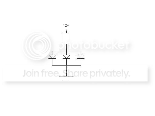
I would reccomend dropping the value of the resistor to 150 Ohms. I believe 100 may be pushing the max I limit of the LEDs.
However, I have not taken any measurements and am assuming that 12V is applied to the circuit when the dash lighting is at its brightest and that the LEDs are in parallel with each other sharing common load resistors. I picked 12V because that would yeild about 7 - 10mA through each LED in this configuration.
I will try to take mine apart this weekend. However, I moved into a new apartment and will be in the middle of unpacking, so not sure if I will get a chance. If anyone does, try to figure out if they are indeed configured as above and measure the voltage across the resistors (from one end of the resistor to the other, not to ground) and across the LEDs. Then, if the circuit is built as above, measure from the top of the resistor to the cathode (ground side) of the LEDs. These numbers will make it easy to re-design. If they are configured a different way let me know. I doubt they are in series, since a failure of one will cause the others to go out.
If each set of three LEDs are in series, then the 150 Ohm should work as well, but you could get away with 100 ohms in that case.
I would reccomend dropping the value of the resistor to 150 Ohms. I believe 100 may be pushing the max I limit of the LEDs.
However, I have not taken any measurements and am assuming that 12V is applied to the circuit when the dash lighting is at its brightest and that the LEDs are in parallel with each other sharing common load resistors. I picked 12V because that would yeild about 7 - 10mA through each LED in this configuration.
I will try to take mine apart this weekend. However, I moved into a new apartment and will be in the middle of unpacking, so not sure if I will get a chance. If anyone does, try to figure out if they are indeed configured as above and measure the voltage across the resistors (from one end of the resistor to the other, not to ground) and across the LEDs. Then, if the circuit is built as above, measure from the top of the resistor to the cathode (ground side) of the LEDs. These numbers will make it easy to re-design. If they are configured a different way let me know. I doubt they are in series, since a failure of one will cause the others to go out.
If each set of three LEDs are in series, then the 150 Ohm should work as well, but you could get away with 100 ohms in that case.
Thread Starter
Senior Member
SL Member
Joined: Feb 2005
Posts: 2,087
From: St. Louis, MO
Heh, heh, heh. It sure does help. I think you guys have a winner here.  I am going with a 330 ohm and 2 each 430 ohm in parallel and work from there. I think that would be safe on the circuit and take no time to do. I'm thinking parallel
I am going with a 330 ohm and 2 each 430 ohm in parallel and work from there. I think that would be safe on the circuit and take no time to do. I'm thinking parallel
Senior Member
Scikotics
SL Member
Joined: Nov 2004
Posts: 9,731
From: Minneapolis, MN
Originally Posted by ScionDad
Heh, heh, heh. It sure does help. I think you guys have a winner here. I am going with a 330 ohm and 2 each 430 ohm in parallel and work from there. I think that would be safe on the circuit and take no time to do. I'm thinking parallel
I am going with a 330 ohm and 2 each 430 ohm in parallel and work from there. I think that would be safe on the circuit and take no time to do. I'm thinking parallel


Senior Member
SL Member
Joined: May 2005
Posts: 108
check out the thread about the same thing on clubsciontc's forums, some guy got around this buy physically raising the LEDs off the PCB using thick copper wire salvaged from a pair of jumper cables. they look just as bright as the dash when raised.

Senior Member
Scikotics
SL Member
Joined: Nov 2004
Posts: 9,731
From: Minneapolis, MN
Originally Posted by kenwoodx2
So for those of us less willing to monkey around with our gauges. Any clue to an aftermarket gauge coming out for the tC with blue illumination?
Good idea on raising the LEDs up off the board. Do they have pics of the results on that site?
Senior Member
Scikotics
SL Member
Joined: Nov 2004
Posts: 9,731
From: Minneapolis, MN
Anyone have an idea of how much the gauge cluster board sells for? I have a couple of ideas for some lighting changes that will require me to construct a control circuit for them. I would need one I could play with for a while to determine sources for my inputs and outputs. Maybe something that could be available for others if I can get it all together. Just an idea (there is no nerdy emoticon on here or I would use it now  )
)
)
Senior Member
SL Member
Joined: May 2005
Posts: 108
http://clubsciontc.com/modules.php?n...=asc&start=120
i remember there being more pics on the guys website i guess click on his profile or something to find the link, i don'jt have it handy
i remember there being more pics on the guys website i guess click on his profile or something to find the link, i don'jt have it handy
Senior Member
Scikotics
SL Member
Joined: Nov 2004
Posts: 9,731
From: Minneapolis, MN
Originally Posted by mushrew
http://clubsciontc.com/modules.php?name=Forums&file=viewtopic&t=1863&postdays=0&postorder=asc&start=120
i remember there being more pics on the guys website i guess click on his profile or something to find the link, i don'jt have it handy
i remember there being more pics on the guys website i guess click on his profile or something to find the link, i don'jt have it handy
Thanks for posting !