


BLUE Led conversion people - Problem/Solution!?


Senior Member


Scikotics
SL Member
Joined: Nov 2004
Posts: 9,731
From: Minneapolis, MN

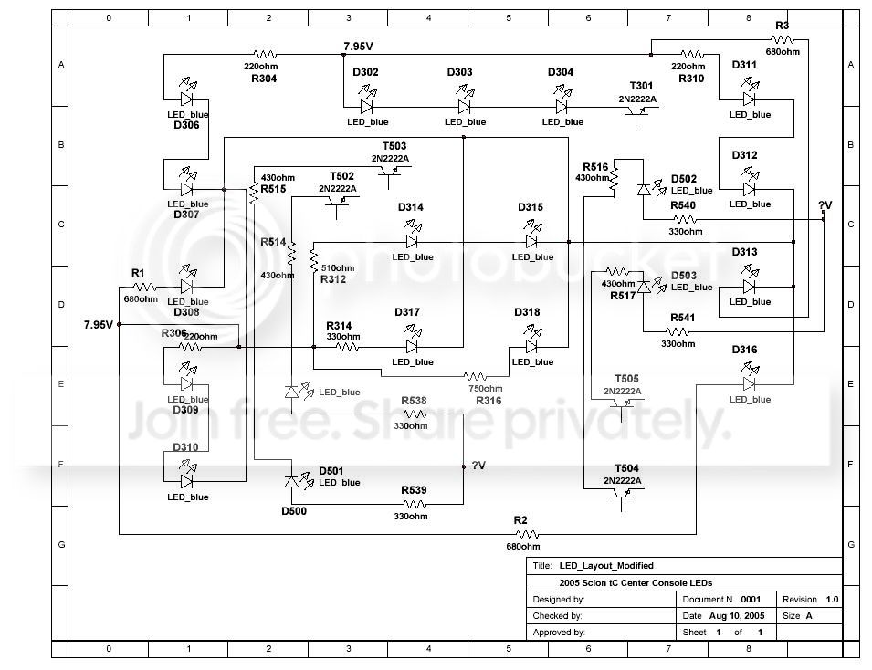
Thanks for the good words! Here is the modified schematic for those interested. Keep in mind I need to test this, but I think this will get us there as long as the regulator can handle it (which I am sure it can). It shows the modifed circuit, added R1 - R4 and swapped out R304, R306 and R310. We can keep our fingers crossed anyway...
Senior Member
Scikotics
SL Member
Joined: Nov 2004
Posts: 9,731
From: Minneapolis, MN
I just finished modifying the circuit for the upper left three buttons and testing them. Here are a couple of pictures. I blocked out the dial and spot for the clock because neiter are in, so those LEDs drown the camera shot unless I cover them. Once gives a comparison with the gauge lights. I think they will match perfectly! When I complete the rest I will post a full write up and pictures.


Senior Member
Scikotics
SL Member
Joined: Nov 2004
Posts: 9,731
From: Minneapolis, MN
Originally Posted by tanlogic
That looks great!
Will this be the same if someone were to go with white?
Will this be the same if someone were to go with white?
I'll post pics of the whole thing later when it is complete!
I did end up using different sized resistors than I originally figured for, so I will post the new values as well once I know it all looks right.

 That looks SWEET
  I guess after seeing it Blue and dim for 7 months...WOW.
Senior Member
Scikotics
SL Member
Joined: Nov 2004
Posts: 9,731
From: Minneapolis, MN
Here it is.. complete! I soldered my LCD on it to see how it looks. I would have liked to have had smaller resistors on hand.. but the 1/8 W is the smallest I had and worked great. I am in the process of getting some smaller ones and more LEDs and I will ship the other one complete back to you ScionDad, you should just have to solder on your LCD and pop it in! . Thanks for letting me borrow it! I want to drive with them for a couple of days anyway to make sure all connections are good, power supplies are OK, etc. But Everything measured out good when I was finshed. I will post the pics of the board and a full write-up of how it is done this weekend, probably tomorrow.. but here are some pics...



And of course, the aftertime :
And of course, the aftertime :

Senior Member
SL Member
Joined: Mar 2005
Posts: 180
From: San Francisco, CA
wow... nice... i have ordered my leds and will do it soon... waiting for a nice write-up about making them not dim anymore! thanks! props to engifineer!! you should do blue for the head unit also...


Member
SL Member
Joined: Jul 2005
Posts: 42
Hey engifineer.. seems like you and i where working on the same thing at the same time... i have them done already (pics below) but i didn't used any resistance... i just changed the circuit to series-parallel instead of a whole series and it works just fine....
By the way... engifineer i screwed up my lcd by hitting it accidentaly with the plier... if you know where can i get a replacement please let me know...
engifineer i will do a diagram of how i got it done so you can check it and tell me if what i did is right or not.... based on some numbers that i threw in, 8 of my bulbs are supposed to be working with 5.6V and four of them working with 2.8V (5.6/2).
Check the pics below.


[/img]
By the way... engifineer i screwed up my lcd by hitting it accidentaly with the plier... if you know where can i get a replacement please let me know...
engifineer i will do a diagram of how i got it done so you can check it and tell me if what i did is right or not.... based on some numbers that i threw in, 8 of my bulbs are supposed to be working with 5.6V and four of them working with 2.8V (5.6/2).
Check the pics below.
[/img]

Senior Member
Scikotics
SL Member
Joined: Nov 2004
Posts: 9,731
From: Minneapolis, MN
^^ Looks good! I added the resistance to keep from killing the 7808 regulator or burning the LEDs up sooner than later. I wanted to make them as bright as the gauges without drawing any more current than necessary. There should be some headroom at the regulator, but I did not want to push it too hard. It looks like you ran your bottom LED in parallel with the second one? I did that with the blue and there was a definite noticeable difference in brightness between them (which may not be so noticeable with the white), so I worked on it a little so they are all operating on the same forward current.
A little LED info for everyone interested: Do keep in mind on your voltages that the LEDs will always read approx 2.6 - 2.8 V across them (for the blues and whites we use). An LED has very high resistance untill its minimum forward voltage is reached. At that point, that voltage (2.6V here) is dropped accross the LED, and the rest is dropped across your wiring (which has very very low resistance) So to figure the current through the circuit you divide whats left of the circuit voltage after the LED is subtracted and divide that by the other resistances in the circuit. So if you apply 5V, lets say, to a 2.6V LED and use no resistance in series, your circuit current is 2.4V/(near zero resistance), which is very high. This is why we always want a resistance in series with the LEDs. For the clock I actually shorted across the resistor, but they are in series, so the voltage is almost exactly equal to the three forward voltages, so the measure current through those three are actuall approx 1mA believe it or not!
I am in the middle of some stuff today, but will work on a full write up as I can, hopefully today. Thanks for the good words!
A little LED info for everyone interested: Do keep in mind on your voltages that the LEDs will always read approx 2.6 - 2.8 V across them (for the blues and whites we use). An LED has very high resistance untill its minimum forward voltage is reached. At that point, that voltage (2.6V here) is dropped accross the LED, and the rest is dropped across your wiring (which has very very low resistance) So to figure the current through the circuit you divide whats left of the circuit voltage after the LED is subtracted and divide that by the other resistances in the circuit. So if you apply 5V, lets say, to a 2.6V LED and use no resistance in series, your circuit current is 2.4V/(near zero resistance), which is very high. This is why we always want a resistance in series with the LEDs. For the clock I actually shorted across the resistor, but they are in series, so the voltage is almost exactly equal to the three forward voltages, so the measure current through those three are actuall approx 1mA believe it or not!
I am in the middle of some stuff today, but will work on a full write up as I can, hopefully today. Thanks for the good words!
Senior Member
Scikotics
SL Member
Joined: Nov 2004
Posts: 9,731
From: Minneapolis, MN
Originally Posted by viro
Here is the diagram of how i got it done... please check it engifineer.... any comments are welcome....
Please someone that knows about a LCD screen please let me know....

Please someone that knows about a LCD screen please let me know....
