Front LED Turn Signals DIY
 08-01-2011, 05:38 AM
#1
Senior Member

SL Member
Thread Starter

Join Date: Mar 2011
Location: Nashua, NH
Posts: 2,102
maybe this should be sticky?
LED Turn Signals Without HyperFlashing DIY
Here is the LED vs Stock Bulb.
LED on right of course
If you want to swap your stock bulbs with any 7440 LED then you will run into hyper flashing problem that looks like this:
In order to fool the relay, you have to be able to simulate the stock bulb.
Stock bulb is roughly 22watts which draws ~2Amps of current
Most high powered LEDs will not draw any more than 0.2 Amps.....
Soooo
You have to use a resistor!
The resistor will have to be placed in parallel with the LED and draw ~2Amps
In order to draw 2 Amps you need a 6 ohm resistor. (Voltage = Current x Resistance)
Im not going to go into details that you dont really need to know...
Things you'll need:
2 LEDs
2 6-Ohm resistors rated for 50 watts or higher
(http://www.superbrightleds.com/cgi-b...dresistor.html)
2 wire splicers - Actually....NO! i was hyperflashing because the connection wasnt reliable so I soldered in the wires
Wires
Metal Zip-ties
Aluminum Heat Sink (recommended)
AND LOTTA LOTTA PATIENCE! THIS TAKES TOO LONG FOR SOMETHING SO SIMPLE, IMO THIS IS THE LEAST REWARDING MOD
The Resistor MUST be mounted to a sanded surface or a heatsink. No resistor by itself is rated for more than ~10watts. All high powered resistors are assumed to be mounted on a heat sink and it never get mentioned! A 50W resistor by itself will handle no more 3-5Watts. If heatsink is not used then the resistor can break down at any moment. It can result in a short circuit or a micro rapture from the inside. I understand that in most applications a turn signal will not be on for more than 5-10 seconds which will not get the resistor overly hot but over time it could still fail. Having the hazard lights on is primary reason for this precaution.
To give you some Idea: After 10-15 min of having hazards on, the temp of my resistor was 180 degrees F and the heat sink it is on was 120.
If you dedicated enough then keep reading...
Step1
Splice into the Positive lead on the socket only.
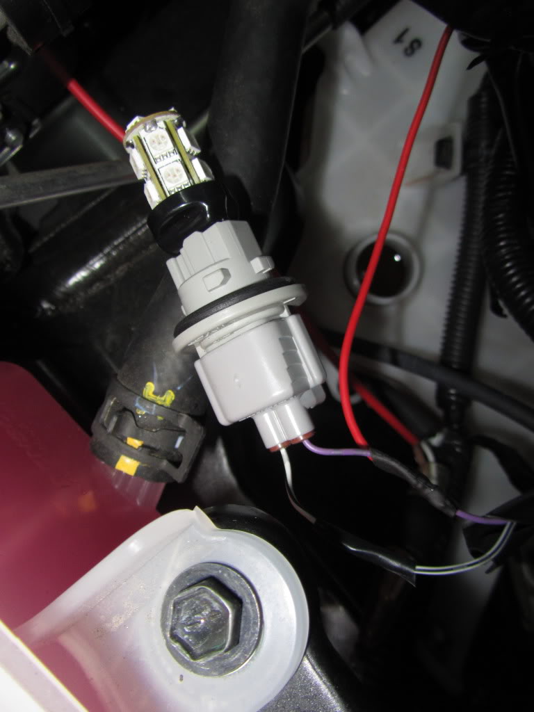
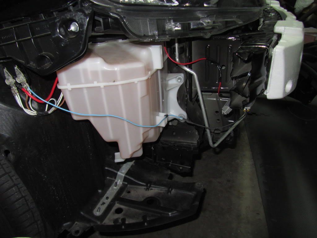
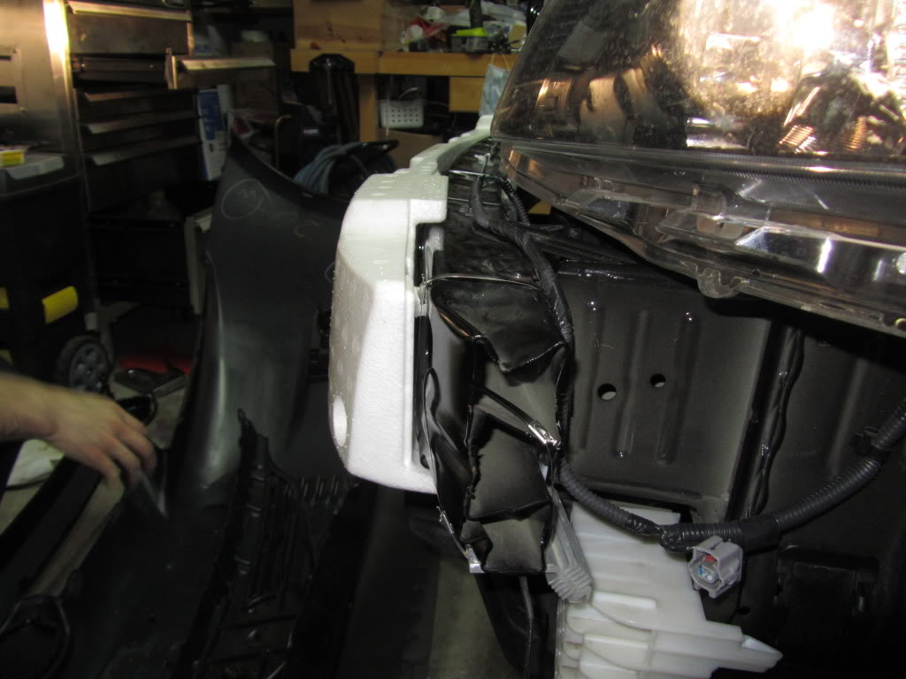
Step2
Find a location to mount the resistor. I picked the front bumper.
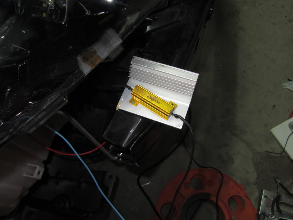
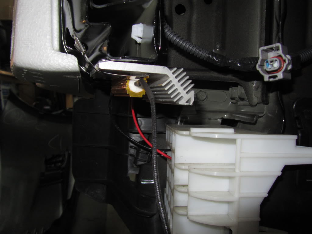
Step3
Sand the flat surface that the resistor will be touching or mount it to an aluminum heat sink.
(My friend had random aluminum heatsink around his house so I used em)
Step4
Connect the Resistor in parallel with the socket
-positive from the socket to one end of the resistor
-another end of the resistor can be grounded to anything on a car
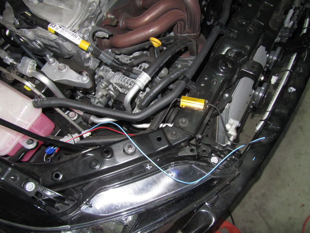
Step5
Turn on and make sure that no hyper flashing is occurring
Step6
Mount the Resistor with metal zip ties to a chassis or the aluminum heat sink to a chassis.
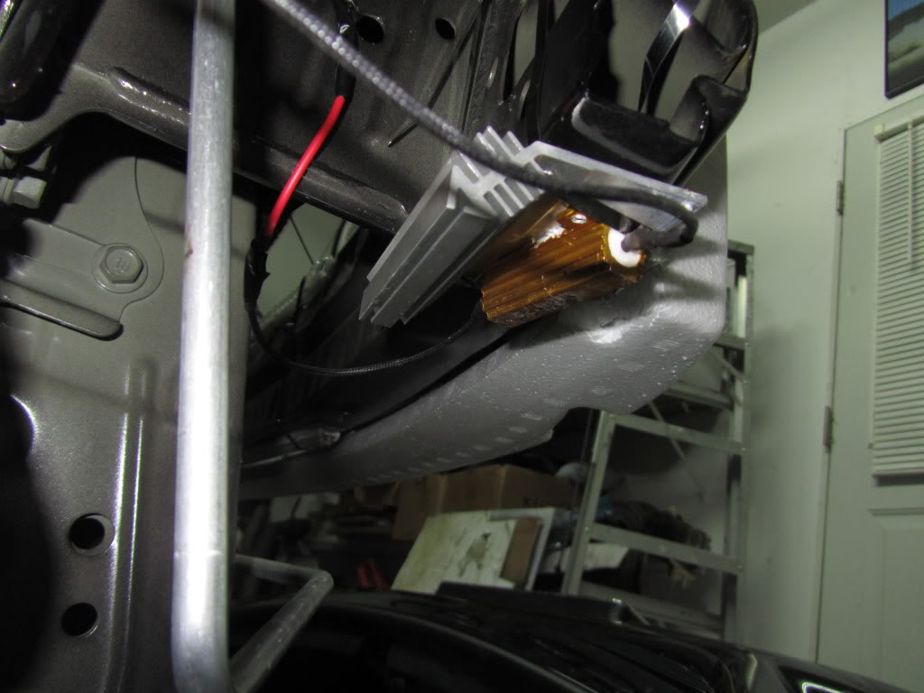
other side:
Video of completed set up:
If you aren't discouraged to do the rears then YOU NEED TO GET A LIFE
YOU'RE DONE!
LED Turn Signals Without HyperFlashing DIY
Here is the LED vs Stock Bulb.
LED on right of course
If you want to swap your stock bulbs with any 7440 LED then you will run into hyper flashing problem that looks like this:
In order to fool the relay, you have to be able to simulate the stock bulb.
Stock bulb is roughly 22watts which draws ~2Amps of current
Most high powered LEDs will not draw any more than 0.2 Amps.....
Soooo
You have to use a resistor!
The resistor will have to be placed in parallel with the LED and draw ~2Amps
In order to draw 2 Amps you need a 6 ohm resistor. (Voltage = Current x Resistance)
Im not going to go into details that you dont really need to know...
Things you'll need:
2 LEDs
2 6-Ohm resistors rated for 50 watts or higher
(http://www.superbrightleds.com/cgi-b...dresistor.html)
2 wire splicers - Actually....NO!
Wires
Metal Zip-ties
Aluminum Heat Sink (recommended)
AND LOTTA LOTTA PATIENCE! THIS TAKES TOO LONG FOR SOMETHING SO SIMPLE, IMO THIS IS THE LEAST REWARDING MOD
The Resistor MUST be mounted to a sanded surface or a heatsink. No resistor by itself is rated for more than ~10watts. All high powered resistors are assumed to be mounted on a heat sink and it never get mentioned! A 50W resistor by itself will handle no more 3-5Watts. If heatsink is not used then the resistor can break down at any moment. It can result in a short circuit or a micro rapture from the inside. I understand that in most applications a turn signal will not be on for more than 5-10 seconds which will not get the resistor overly hot but over time it could still fail. Having the hazard lights on is primary reason for this precaution.
To give you some Idea: After 10-15 min of having hazards on, the temp of my resistor was 180 degrees F and the heat sink it is on was 120.
If you dedicated enough then keep reading...
Step1
Splice into the Positive lead on the socket only.
Step2
Find a location to mount the resistor. I picked the front bumper.
Step3
Sand the flat surface that the resistor will be touching or mount it to an aluminum heat sink.
(My friend had random aluminum heatsink around his house so I used em)
Step4
Connect the Resistor in parallel with the socket
-positive from the socket to one end of the resistor
-another end of the resistor can be grounded to anything on a car
Step5
Turn on and make sure that no hyper flashing is occurring
Step6
Mount the Resistor with metal zip ties to a chassis or the aluminum heat sink to a chassis.
other side:
Video of completed set up:
If you aren't discouraged to do the rears then YOU NEED TO GET A LIFE
YOU'RE DONE!


 09-05-2011, 07:25 PM
#6
Senior Member
SL Member
Join Date: Mar 2009
Posts: 184
so i finally found the flasher relay for the LED mods so you dont have to install all 4 of the load resistors. the new relay has the resistance needed to solve the hyper-flash issue.
the stock relay is a Tridon LM449
the replacement part number is 81980-55030 (toyota CF18 ALT). its a 8 pin relay and should say "for led" on the side. they have them on autolumination.com
if you replace this one relay for $15, you can save a lot of time doing each individual load resistor.
i am not 100% on the location of the relay but it sounds like its located in the juction box under the driver side dash on the left side. once i get the parts in and get them installed, ill update this post.

Thread
Thread Starter
Forum
Replies
Last Post
xBSciontist
Scion xB 1st-Gen Aero & Exterior
6
06-18-2019 03:06 PM
randomsuper
Scion xB 2nd-Gen Aero & Exterior
20
06-13-2015 10:56 AM
Opr8r
Scion xB 1st-Gen Aero & Exterior
20
02-25-2004 11:29 PM