
How Can I Invert the turn signal lighting to stay on and


Thread Starter
Senior Member
SL Member
Joined: Nov 2005
Posts: 13,373
From: WORLD WIDE Flossin
if im able to get this done.. of course ill thank those who helped.. and i will put a good DIY on this.. waiting for Onzium or Tweetertc to shed some more light and help


Senior Member
Scikotics
SL Member
Joined: Oct 2006
Posts: 2,170
From: South SoCal, California
Ha! I remember I used to do this with the sidemarkers for my previous cars: Lancer, Galant, Civic, and Accord. All with sidemarkers, we used to call it cheek lights. 
What it does is when you turn on your parking lights, the turn signal bulb turns on with it and blinks if you turn on your turn signal **** or stick, whatever you wanna call it.
I don't know if this trick will work with a tC, so be ready with replacement fuses and/or bulbs. I'm not quite sure about the car's trigger for lighting, if it's positive or negative trigger. You don't need a relay or anything complicated. Just a single copper wire will do the trick. If my memory serves me right, here's how it goes:
Disclaimer: I'm not responsible for any damage you might inflict your car. So proceed at your own risk!!! I suggest experiment with an older car! Or your friend's!
For one side only. Do this for the other side too:
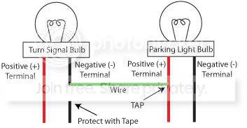
1.) Cut the negative terminal of the turn signal.
2.) Connect the wire to the negative terminal of the turn signal bulb.
3.) Tape the other end of the negative terminal for protection. You will not use it anymore.
4.) Splice and tap the other end of the wire to the positive terminal of the parking light. Again, splice and tap. Don't cut.
5.) Tape with electrical tape for protection. Or use a T-tap connector.
6.) Read disclaimer twice.
7.) Enjoy!
What it does is when you turn on your parking lights, the turn signal bulb turns on with it and blinks if you turn on your turn signal **** or stick, whatever you wanna call it.
I don't know if this trick will work with a tC, so be ready with replacement fuses and/or bulbs. I'm not quite sure about the car's trigger for lighting, if it's positive or negative trigger. You don't need a relay or anything complicated. Just a single copper wire will do the trick. If my memory serves me right, here's how it goes:
Disclaimer: I'm not responsible for any damage you might inflict your car. So proceed at your own risk!!! I suggest experiment with an older car! Or your friend's!
For one side only. Do this for the other side too:
1.) Cut the negative terminal of the turn signal.
2.) Connect the wire to the negative terminal of the turn signal bulb.
3.) Tape the other end of the negative terminal for protection. You will not use it anymore.
4.) Splice and tap the other end of the wire to the positive terminal of the parking light. Again, splice and tap. Don't cut.
5.) Tape with electrical tape for protection. Or use a T-tap connector.
6.) Read disclaimer twice.
7.) Enjoy!
Senior Member
Scikotics
SL Member
Joined: Oct 2006
Posts: 2,170
From: South SoCal, California
Nope. I have had my Accord with them on for more than 4 years, with no issues. And the other "family" cars for like 1-2 years. My Accord had those sidemarkers mounted at the fenders. I think I used 14 or 16 AWG.
Thread Starter
Senior Member
SL Member
Joined: Nov 2005
Posts: 13,373
From: WORLD WIDE Flossin
can u make a quickie diagram of what your talking about.. the parking bulb has 2 wires going to it.. and im not sure wether you want me to cut the wire or in other words what you mean by "terminal"
EDIT!!
is this what your saying to do

EDIT!!
is this what your saying to do


pete it hink what he meant was take that green copper wire and tap that into the positive wire of the parking light, looks like in that pic you have it goin from the negative of the blinker to the postive of the blinker. i oculd be wrong tho
Thread Starter
Senior Member
SL Member
Joined: Nov 2005
Posts: 13,373
From: WORLD WIDE Flossin
ill wait until he is done with the diagram dave.. hey i never got to answer you PM can you shoot it to me again i deleted it by mistake
waiting on daskid now to correct my diagram lol or for Ozium or Tweetertc to chime in again...
waiting on daskid now to correct my diagram lol or for Ozium or Tweetertc to chime in again...


Senior Member
SL Member
Joined: Aug 2006
Posts: 1,520
From: Pittsburgh, PA
Hopefully it really does work though on our cars and doesn't throw the sensor that reads voltage drops and then we would have really fast blinking turn signals like all the ricer kids with body kits that don't come with all the right parts.
Senior Member
Scikotics
SL Member
Joined: Oct 2006
Posts: 2,170
From: South SoCal, California
Sorry for the wait guys. The bossman kept on passing by. :D
It's pretty straight-forward. Please note that I haven't tested this on a tC. But this works perfectly fine with Lancers, Galants, Civics, and Accord. If ya'll can find out if the tC has the same trigger (positive or negative) as with those cars, then it should work just fine.
EDIT: This only works when the parking lights are on. If you want to keep them running with the parking lights off, you would have to get a relay for that.
Read disclaimer!!! I dun want you to sue my a$$ if it goes nuts!
Senior Member
SL Member
Scion Evolution
Joined: Feb 2006
Posts: 566
From: Chicago, IL
NOOOOO!!!
dont do that...
**** i wish i wasnt at work to make a diagram...
the relay would work... i thought about it a little more sitting here bored, looking at my car thinking if it would look cool or not... i will get one up when i get home guys...
dont do that...
**** i wish i wasnt at work to make a diagram...
the relay would work... i thought about it a little more sitting here bored, looking at my car thinking if it would look cool or not... i will get one up when i get home guys...

Former Sponsor
Scikotics
SL Member
Joined: Apr 2005
Posts: 849
From: Bay Area, CA
Thread Starter
Senior Member
SL Member
Joined: Nov 2005
Posts: 13,373
From: WORLD WIDE Flossin
Originally Posted by Oznium_com
http://www.oznium.com/relay40
Get one of these for each side
Get one of these for each side
Originally Posted by tweetertc
NOOOOO!!!
dont do that...
**** i wish i wasnt at work to make a diagram...
the relay would work... i thought about it a little more sitting here bored, looking at my car thinking if it would look cool or not... i will get one up when i get home guys...
dont do that...
**** i wish i wasnt at work to make a diagram...
the relay would work... i thought about it a little more sitting here bored, looking at my car thinking if it would look cool or not... i will get one up when i get home guys...
im gonna wait on some more diagrams..
Senior Member
Scikotics
SL Member
Joined: Oct 2006
Posts: 2,170
From: South SoCal, California
Or what you can do is replace the turn signal bulb with a double contact bulb. That would make the bulb looks like it blinks from approx 60% power to 100% power. The bulb looks like it never turns off, but what really happens is one contact blinks from 0% power to 100% power and the other contact stays on for approx 60% of the power.
Former Sponsor
Scikotics
SL Member
Joined: Apr 2005
Posts: 849
From: Bay Area, CA
