
How To: Daylight Running Lights - Beta Version


Thread Starter
Senior Member
Scikotics
SL Member
Joined: Oct 2006
Posts: 2,170
From: South SoCal, California
-Disclaimer-
I won�t be held liable of anything that goes wrong in this project. I have never tested this circuit in my own car because I want the lights to just turn on at 60% of the output power, therefore, no pics of the actual installation. I am still on the process of knowing on how to make it work. This circuit will make the headlights light up at 100% power when you start to drive. Please take note that glare will be produced and might cause irritability to oncoming traffic. Please use at your own risk.
Items Needed:
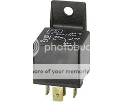
5-pin 12V 30A/40A SPST NONC Automotive Relay (4 units)
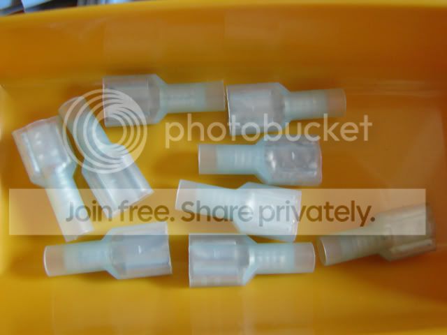
� Push-on Terminal for 16-14 AWG Wire (1 pack)
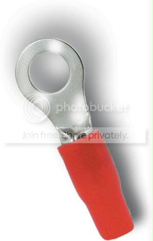
Car Battery Ring Terminal (1 pack)
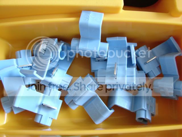
16-14 AWG T-Taps Electrical Connector Terminal (1 pack)
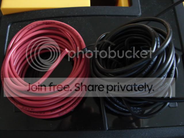
16 or 14 AWG Wire (25 ft long approx.)
20A Blade Fuse (3 pieces or more for reserves in case you blow them up)
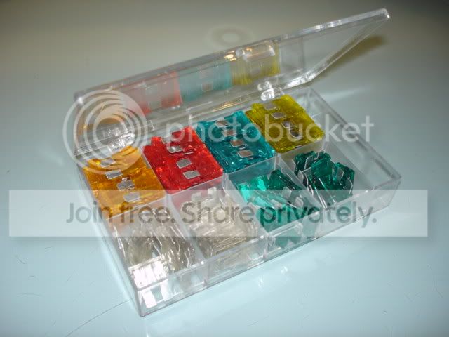
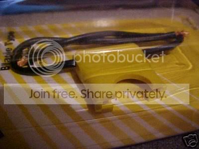
In Line Blade Fuse Holder (3 pieces)
Tools:
Crimper
Wire Cutter
Soldering Iron
Lead-Free Solder
Electrical Tape or Shrink Tubes
Gloves (maybe)
Protective Goggles
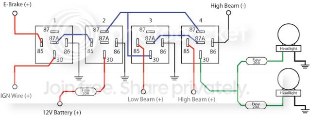
Simple Connection Diagram
Simple Explanation:
1. Solder the wire to the � push-on terminals and crimp it to close.
2. Use the � push-on terminals for all connections on the relays.
3. Use the car battery ring terminal to connect a wire to the battery terminal (duhh).
4. Bound the four relays by wrapping it with electrical tape and cover the terminals for it not to be wet.
Installation:
1. Disconnect the connection on the negative (-) terminal of the car battery.
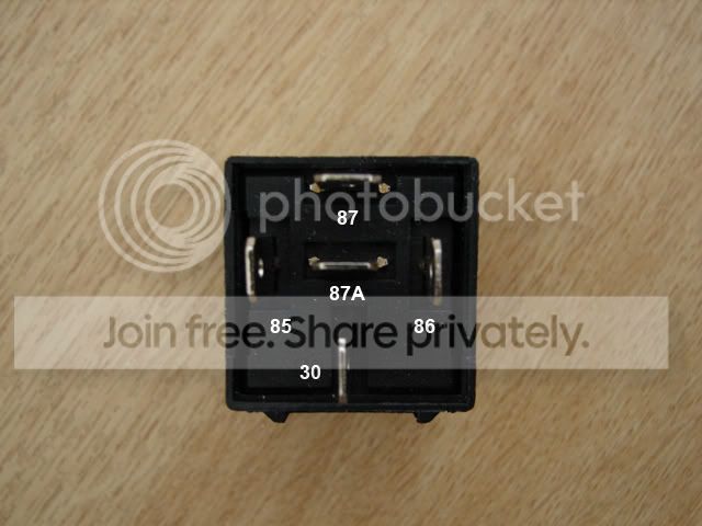
2. All Pin 86 of the relays 1, 2, and 3 should be connected to a ground source. I.e. Bolt attached to the chassis and make sure to sand the paint off on the chassis. Or you can run it directly to the negative (-) terminal of the car battery.
3. Tap a wire to the positive (+) of the E-Brake using a T-Tap terminal and connect it to Pin 85 of Relay 1.
4. Tap a wire to the IGN Wire using a T-Tap terminal and connect it to Pin 30 of Relay 1. You can find the IGN wire in the fuse box in the engine bay.
5. Connect Pin 87A of Relay 1 to Pin 85 of Relay 2.
6. Connect Pin 30 of Relay 2 to the Positive (+) terminal of the car battery. Put an in-line fuse holder with a fuse rated 20A.
7. Connect Pin 87 of Relay 2 to Pin 30 of Relay 3 and Pin 87 of Relay 4.
8. Tap a wire to the positive terminal (+) of the Low Beam (either driver or passenger) using a T-Tap terminal and connect it to Pin 85 of Relay 3.
9. Connect Pin 87A of Relay 3 to Pin 87A of Relay 4.
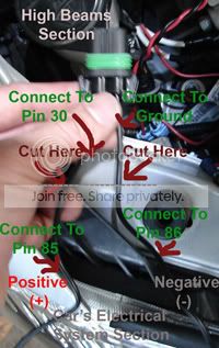
10. Cut the high beam wire on both driver�s and passenger�s side.
11. Connect a wire to the positive terminal (+) of the High Beam coming from the car (either driver or passenger) and connect it to Pin 85 of Relay 4.
12. Connect a wire to the negative terminal (-) of the High Beam coming from the car (same as what you used in step 11) and connect it to Pin 86 of Relay 4.
13. Connect Pin 30 of Relay 4 to both positive (+) terminals of the Headlight. In this case, it�s the high beams.
14. It is recommended to put in-line fuse holders with a fuse rated 20A to each of the headlights for protection.
15. Reconnect the connection on the negative (-) terminal of the car battery.
16. Enjoy yourself with some... (must be in legal age to drink)
Headlight Explanation
Remember to put a fuse holder with a 20A fuse in between Pin 30 of Relay 4 and the positive terminal of the bulb.
This circuit should do the following:
1. Engine off, E-brake up, low beams off, high beams off = DRL off
2. Engine on, E-brake up, low beams off, high beams off = DRL off
3. Engine on, E-brake down, low beams off, high beams off = DRL on
4. Engine on, E-brake down, low beams on, high beams off = DRL off
5. Engine on, E-brake down, low beams off, high beams on = DRL off
6. Engine on, E-brake down, low beams on, high beams on = DRL off
As you could see, the DRL circuit will only and only turn on if the conditions in line number 3 are satisfied.
All comments are welcome and I recommend you to inform me of anything that I might have overlooked.
Again, please read the disclaimer above before proceeding with the project. And remember, this circuit gives out 100% of power not 60%!!!
I am currently testing a similar circuit that will make the DRL give out power at only 60% or less� Keep you guys updated.
Thank you.

I won�t be held liable of anything that goes wrong in this project. I have never tested this circuit in my own car because I want the lights to just turn on at 60% of the output power, therefore, no pics of the actual installation. I am still on the process of knowing on how to make it work. This circuit will make the headlights light up at 100% power when you start to drive. Please take note that glare will be produced and might cause irritability to oncoming traffic. Please use at your own risk.
Items Needed:
5-pin 12V 30A/40A SPST NONC Automotive Relay (4 units)
� Push-on Terminal for 16-14 AWG Wire (1 pack)
Car Battery Ring Terminal (1 pack)
16-14 AWG T-Taps Electrical Connector Terminal (1 pack)
16 or 14 AWG Wire (25 ft long approx.)
20A Blade Fuse (3 pieces or more for reserves in case you blow them up)
In Line Blade Fuse Holder (3 pieces)
Tools:
Crimper
Wire Cutter
Soldering Iron
Lead-Free Solder
Electrical Tape or Shrink Tubes
Gloves (maybe)
Protective Goggles
Simple Connection Diagram
Simple Explanation:
1. Solder the wire to the � push-on terminals and crimp it to close.
2. Use the � push-on terminals for all connections on the relays.
3. Use the car battery ring terminal to connect a wire to the battery terminal (duhh).
4. Bound the four relays by wrapping it with electrical tape and cover the terminals for it not to be wet.
Installation:
1. Disconnect the connection on the negative (-) terminal of the car battery.
2. All Pin 86 of the relays 1, 2, and 3 should be connected to a ground source. I.e. Bolt attached to the chassis and make sure to sand the paint off on the chassis. Or you can run it directly to the negative (-) terminal of the car battery.
3. Tap a wire to the positive (+) of the E-Brake using a T-Tap terminal and connect it to Pin 85 of Relay 1.
4. Tap a wire to the IGN Wire using a T-Tap terminal and connect it to Pin 30 of Relay 1. You can find the IGN wire in the fuse box in the engine bay.
5. Connect Pin 87A of Relay 1 to Pin 85 of Relay 2.
6. Connect Pin 30 of Relay 2 to the Positive (+) terminal of the car battery. Put an in-line fuse holder with a fuse rated 20A.
7. Connect Pin 87 of Relay 2 to Pin 30 of Relay 3 and Pin 87 of Relay 4.
8. Tap a wire to the positive terminal (+) of the Low Beam (either driver or passenger) using a T-Tap terminal and connect it to Pin 85 of Relay 3.
9. Connect Pin 87A of Relay 3 to Pin 87A of Relay 4.
10. Cut the high beam wire on both driver�s and passenger�s side.
11. Connect a wire to the positive terminal (+) of the High Beam coming from the car (either driver or passenger) and connect it to Pin 85 of Relay 4.
12. Connect a wire to the negative terminal (-) of the High Beam coming from the car (same as what you used in step 11) and connect it to Pin 86 of Relay 4.
13. Connect Pin 30 of Relay 4 to both positive (+) terminals of the Headlight. In this case, it�s the high beams.
14. It is recommended to put in-line fuse holders with a fuse rated 20A to each of the headlights for protection.
15. Reconnect the connection on the negative (-) terminal of the car battery.
16. Enjoy yourself with some... (must be in legal age to drink)
Headlight Explanation
Remember to put a fuse holder with a 20A fuse in between Pin 30 of Relay 4 and the positive terminal of the bulb.
This circuit should do the following:
1. Engine off, E-brake up, low beams off, high beams off = DRL off
2. Engine on, E-brake up, low beams off, high beams off = DRL off
3. Engine on, E-brake down, low beams off, high beams off = DRL on
4. Engine on, E-brake down, low beams on, high beams off = DRL off
5. Engine on, E-brake down, low beams off, high beams on = DRL off
6. Engine on, E-brake down, low beams on, high beams on = DRL off
As you could see, the DRL circuit will only and only turn on if the conditions in line number 3 are satisfied.
All comments are welcome and I recommend you to inform me of anything that I might have overlooked.
Again, please read the disclaimer above before proceeding with the project. And remember, this circuit gives out 100% of power not 60%!!!
I am currently testing a similar circuit that will make the DRL give out power at only 60% or less� Keep you guys updated.
Thank you.


Senior Member
SL Member
Scion Evolution
Joined: Oct 2006
Posts: 542
From: Chicago, IL
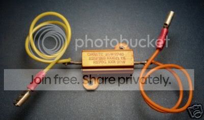
hey in regards to ur post, one way to drop the lights to only 60% power instead of 100% would probably be putting in a 220 ohm resistor inline in the wire connecting to the 12v side of the low beam lights.. what that would do is drop the 12volt signal to around 7.2 volts, that should be enought power to "how you say" just dim the lights. Try that.
Thread Starter
Senior Member
Scikotics
SL Member
Joined: Oct 2006
Posts: 2,170
From: South SoCal, California
Originally Posted by Ragingbull78
hey in regards to ur post, one way to drop the lights to only 60% power instead of 100% would probably be putting in a 220 ohm resistor inline in the wire connecting to the 12v side of the low beam lights.. what that would do is drop the 12volt signal to around 7.2 volts, that should be enought power to "how you say" just dim the lights. Try that.
Senior Member
SL Member
Scion Evolution
Joined: Oct 2006
Posts: 542
From: Chicago, IL
standard drl lights are a different bulb than our 9006's, I had a cavalier once and i think the drl's were on the high beam bulb, i snipped the wire and the drl's were off but the high beams didn't work.
Did you try like a 100ohm resistor just to drop it a little, i know a bulb needs around 9- 10 volts light up..I THINK!! There has to be a resistor in regular DRL's to regulate power going to the bulbs, that is the only way i can think of getting the lights to dim is to drop the power output to it
Did you try like a 100ohm resistor just to drop it a little, i know a bulb needs around 9- 10 volts light up..I THINK!! There has to be a resistor in regular DRL's to regulate power going to the bulbs, that is the only way i can think of getting the lights to dim is to drop the power output to it
Thread Starter
Senior Member
Scikotics
SL Member
Joined: Oct 2006
Posts: 2,170
From: South SoCal, California
Well yeah, basic electronics would have given the resistor to do the job.
I've tested 220 ohms, 100 ohms, approx 34 ohms, approx 32 ohms, and approx 25 ohms. I even bought a 25-ohm rheostat to test the optimum light output without glare, but it still didn't work.
I've noticed the lightbulb lights up at around 10V so below that voltage, it'll turn off. I think there is a special bulb used for DRLs that would turn on even the voltage is just 3V. Or maybe regular accent lightbulbs from Home Depot will do the job?
Some said the system is current-sourcing. I have yet to find how to manipulate that idea.
Still need to do some testing this coming weekend.


Thread Starter
Senior Member
Scikotics
SL Member
Joined: Oct 2006
Posts: 2,170
From: South SoCal, California
Originally Posted by tcridinclean
hey have u figured out how to run the lights at 60% power?
I'll test it this weekend if I have nothing to do. :D

Thread
Thread Starter
Forum
Replies
Last Post
Ferretgrrl
Scion iQ Owner's Lounge
2
Oct 15, 2018 02:50 AM
SkillFreeJake
Scion tC 2G Aero & Exterior
17
Jul 27, 2015 12:34 AM
ScionLife Editor
Scion iM Discussion Lounge
0
Nov 20, 2014 05:20 PM

