
LED Swap (Guages / HVAC)


Senior Member
Scikotics
SL Member
Joined: Nov 2004
Posts: 9,731
From: Minneapolis, MN
Originally Posted by zero01
I really wanna do this but I have no experience in soldering at all. Is there anything important like putting the LED the right way. What does that mean ? Is it like putting the LED in the right way like you do with a battery wtih -/+ ? Does the PCB show which is -/+ or am i going have to do a trail and error thing.
Is there more to this then just soldering some LED out and putting some new ones in ?
Is there more to this then just soldering some LED out and putting some new ones in ?
https://www.scionlife.com/forums/viewtopic.php?t=61793
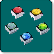
The LEDs have an anode and cathode (corresponding to the + and - portion of the device). If you order the LEDs below,
http://www.lc-led.com/View/itemNumber/98
They will match the ones on the board as far as packaging is concerned. They will have a chopped off corner. Just make sure you solder the new ones in facing the same direction and you will be fine.

Junior Member
Joined: May 2005
Posts: 16
so basicly i should just follow how it looks like on the board then right ? I tried reading your tips and i understood some of it since I work with computers alot but the rest was kind of uneasy for me to understand. I'm thinking about taking a old board from one of my computers and start to solder some stuff out just to practice. Hey do you doing this will void the warranty ?
Senior Member
Scikotics
SL Member
Joined: Nov 2004
Posts: 9,731
From: Minneapolis, MN
Nothing will void the warranty. If they can prove that a mod you make caused the issue at hand, then they can deny warranty coverage for that instance.
Practicing on an old board with surface mount devices is a great idea if you are not familiar with soldering. A surface mount resistor (small, black rectangle shaped device) is close to the size of these LED. The resistors are a little smaller, but if you get those down the LEDs will be easier. And with the model LED I referenced you simply match the way the old one is soldered in. The LEDs I mentioned are about $1.33 a peice, but they are the best match in brightness and have the best color of any others I have found. That is not a high price for the output and view angle specs they offer.
Practicing on an old board with surface mount devices is a great idea if you are not familiar with soldering. A surface mount resistor (small, black rectangle shaped device) is close to the size of these LED. The resistors are a little smaller, but if you get those down the LEDs will be easier. And with the model LED I referenced you simply match the way the old one is soldered in. The LEDs I mentioned are about $1.33 a peice, but they are the best match in brightness and have the best color of any others I have found. That is not a high price for the output and view angle specs they offer.
Junior Member
Joined: May 2005
Posts: 16
thx for helping me out here engifneer i really apperciate it. Do you think i'll need some solder flux for this ? and about Soldering the LED to the PCB does it matter how it's soldered or can I just a enough on it and then leave it alone ?
Here a link to the Solder tips i've been looking at if anything else is interested
http://www.elexp.com/t_solder.htm
Here a link to the Solder tips i've been looking at if anything else is interested
http://www.elexp.com/t_solder.htm

Junior Member
Joined: Apr 2005
Posts: 11
i dont know if this works, but found this on ebay, expensive though.... but might help....
http://cgi.ebay.com/ws/eBayISAPI.dll...976519546&rd=1
http://cgi.ebay.com/ws/eBayISAPI.dll...976519546&rd=1
Senior Member
Scikotics
SL Member
Joined: Nov 2004
Posts: 9,731
From: Minneapolis, MN
Originally Posted by taur1e
i dont know if this works, but found this on ebay, expensive though.... but might help....
http://cgi.ebay.com/ws/eBayISAPI.dll...976519546&rd=1
http://cgi.ebay.com/ws/eBayISAPI.dll...976519546&rd=1
So the ones you listed actually will not fit. I searched and searche (As did others) to find others that fit, and the ones I referenced in my posts are the best match we could find.

Senior Member
SL Member
Team ScioNRG
Joined: Feb 2005
Posts: 360
From: Camp Hill, PA
Ok, can someone break this down simple for me. heres what i want to do.
I want white lights in the following...
rear view mirror blinkers
gauge cluster
center console including the little lighted storage compartment
front and rear dome lights
I want white lights in the following...
rear view mirror blinkers
gauge cluster
center console including the little lighted storage compartment
front and rear dome lights

Junior Member
Joined: Jun 2005
Posts: 11
From: Phoenix
Mehhh i knew it, but am sad that they are, surface mount leds..
engifineer, that's beutiful
my brother wants me to do this to his tC, but I've never worked with surface mount leds.. and all I know about them is that they are EXTREMLY small, which of course means they would be harder to work with, solder ect.. If I'm not a pro solderer, should I even attempt this? I don't want to break my brothers car
Senior Member
Scikotics
SL Member
Joined: Nov 2004
Posts: 9,731
From: Minneapolis, MN
Originally Posted by MTB
Mehhh i knew it, but am sad that they are, surface mount leds..
engifineer, that's beutiful
my brother wants me to do this to his tC, but I've never worked with surface mount leds.. and all I know about them is that they are EXTREMLY small, which of course means they would be harder to work with, solder ect.. If I'm not a pro solderer, should I even attempt this? I don't want to break my brothers car
engifineer, that's beutiful
my brother wants me to do this to his tC, but I've never worked with surface mount leds.. and all I know about them is that they are EXTREMLY small, which of course means they would be harder to work with, solder ect.. If I'm not a pro solderer, should I even attempt this? I don't want to break my brothers car
Junior Member
Joined: Jun 2005
Posts: 11
From: Phoenix
I havn't studied it but I've seen pics and yea.. they're surface mount LEDs (same thing)
they might end up being a little dim if you get any colors besides orange red or yellow.. they're orange (on tc) origanolly and orange usually runs on less volts than any other colors besides red and yellow...
they might end up being a little dim if you get any colors besides orange red or yellow.. they're orange (on tc) origanolly and orange usually runs on less volts than any other colors besides red and yellow...


Member
SL Member
Joined: Apr 2005
Posts: 45
From: Richmond, KY
Anyone have 1have an extra blue LED from this project? I did my gauges in red, but i want my AC button in Blue. Cant see spending the full amount for the sample pack again. Ill pay a few bucks if needed or trade for some red ones if you want your defrost that color.
Send a PM if your able or willing
Thanks.
Send a PM if your able or willing
Thanks.

Senior Member
SL Member
Joined: Feb 2004
Posts: 358
From: Orlando, FL
Well guys... I guess I did it too..
today I had 50 Red LEDs waiting for me on my bed along with those "cold heat" soldering tools.. (kinda cool)
anywho.. I got stuck along the way...
Those damn needles will not come off for S**t!! lol I tried and tried and they will simply not come off! what do I do?
and also.. how would I know what side is what when I'm putting the new leds on the board? He said it matters what way you put them...
Thanks a lot for the help
-Emo
Senior Member
Scikotics
SL Member
Joined: Nov 2004
Posts: 9,731
From: Minneapolis, MN
Use the two spoon method and they will come off. You have to pry a little harder than feels right, but they will come off. Be careful, mine almost hit me  Just place peices of paper towel on either side of the needle and use two spoons to pry evenly.
If you examine the LEDs, there is one corner with a chamfer on it. Just make sure they line up the same way as the old ones and you will be golden
If you examine the LEDs, there is one corner with a chamfer on it. Just make sure they line up the same way as the old ones and you will be golden

Senior Member
SL Member
Joined: Feb 2004
Posts: 358
From: Orlando, FL
Originally Posted by panasoanic
9) We will now desolder the LCD panel. THE LCD PANEL ON THE CONSOLE IS NOT SOCKETED LIKE IT IS ON THE GAUGE CLUSTER. I learned this the hard way and cracked my LCD screen. If you screw this up, you will have to purchase a whole other HVAC computer as the LCD is not sold individually as a repair part. If you can find a replacement computer for cheap, please let me know. Anyway, here is the procedure for removing the LCD panel:
First, use desoldering braid to reheat and suck up the solder along the leads of the LCD on the back of the PCB. You'll know you're done when you can see holes around the leads of the LCD on the circuit board.
Second, remove the two screws holding in the white plastic surround.
Third, *gently* pry up on the LCD by lifting the white surround away from the board. You may have to heat up the leads of the LCD on the underside of the circuit board to finally free them from any residual solder.
http://img61.imageshack.us/my.php?image=lcdleds1qu.jpg
I unscrewed the screws that hold the white plastic and started bending the LCD pins VERY SLOWLY and gently until I exposed the LEDs on the board so I can have enough room to work... you may need a second person holding the board until you remove the leds but that's about it..
And I would like to thank panasoanic for making this how to because I would have never done it by myself.

also... I know how people were saying that the new LEDs draw more current from the center console so they look dimmer.. well in my case it made my Head unit a lot dimmer and not the LEDs..lol witch is a good thing since I'll be replacing the HU anyway...
you can see the difference here...

-Emo